A reaction force support for anchor rod pull-out test and its application method

A technology of pull-out test and reaction force support, which is applied in the field of bolt pull-out test and reaction force support, can solve problems such as irregularities, unbalanced force, embedded rock and soil, etc., and achieve strong operability and transferability Convenient and widely applicable effects

Active Publication Date: 2020-09-15
CHANGAN UNIV
View PDF8 Cites 0 Cited by
  • Summary
  • Abstract
  • Description
  • Claims
  • Application Information

AI Technical Summary

Problems solved by technology

[0005] (1) There is no unified form of backing plate in the anchor pullout test, the form is simple and diverse, and it is not standardized, and it is prone to eccentric tension due to unbalanced force;
[0006] (2) It is impossible to accurately measure the real anchoring force of the bolt
If the diameter of the center hole of the reaction backing plate is too small, the displacement and movement of the grouting body will be restricted. The test data is often the frictional resistance between the anchor and the grouting body, which cannot truly reflect the pullout force of the anchor;
[0007] (3) For the soft and loose rock and soil mass, when the area of ​​the reaction backing plate is similar to the area of ​​the jack base, under the action of strong pressure, the reaction backing plate is easy to crush the rock and soil mass behind, and then embedded in the rock and soil mass, resulting in The range of the jack is not enough, and it needs to be pulled many times, which eventually leads to the fact that the pulling data cannot be guaranteed to be true and reliable;
[0008] (4) For the situation where the position of the anchor rod is high or there is no support below it, the ordinary backing plate is not easy to fix, or it is not easy to center, and the operability is poor

Method used


Image

  • A reaction force support for anchor rod pull-out test and its application method
  • A reaction force support for anchor rod pull-out test and its application method
  • A reaction force support for anchor rod pull-out test and its application method

Examples


Embodiment Construction

[0033] The present invention will be described in detail below in conjunction with the accompanying drawings.

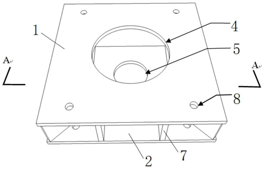
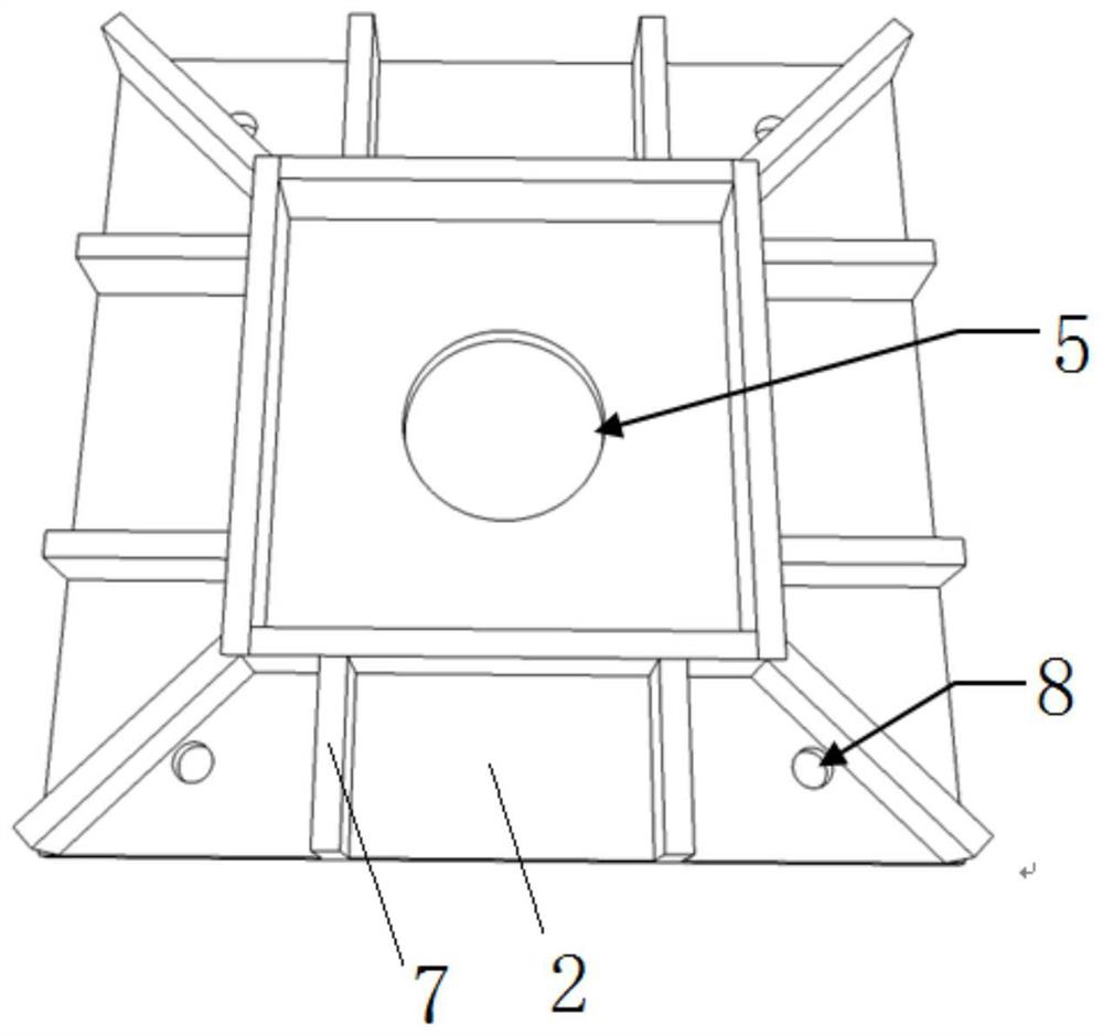
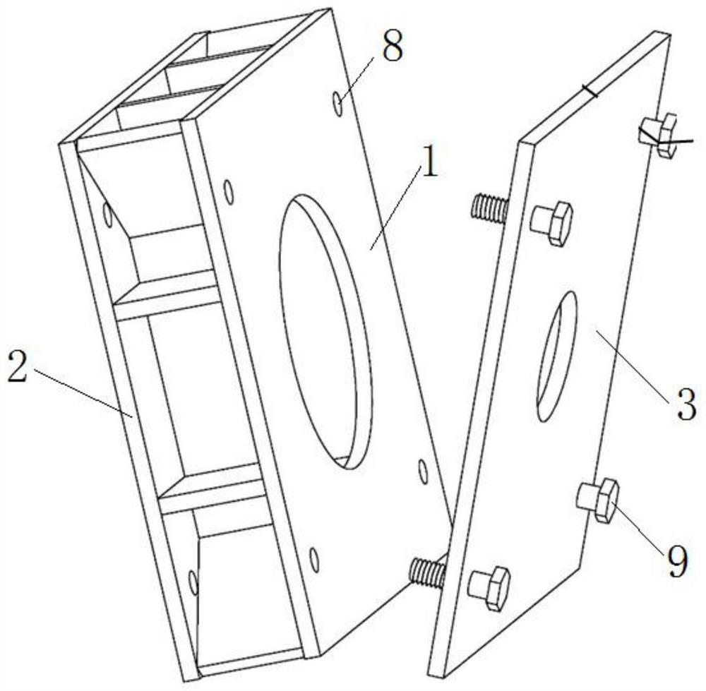
[0034] see figure 1 , figure 2 and image 3 , the novel reaction force bearing used for anchor pullout test of the present invention, comprises reaction backing plate and auxiliary backing plate.

[0035] Wherein, the reaction backing plate includes two identical first steel plates 1 and second steel plates 2, the first steel plates 1 and the second steel plates 2 are connected by a plurality of steel plates 7, and the two ends of each steel plate 7 are respectively welded on On the first steel plate 1 and the second steel plate 2, the height of the steel sheet 7 is 10 cm. The steel sheet 7 is made of the same material as the first steel plate 1 . The center of the first steel plate 1 is provided with the first circular hole 4, and the center of the second steel plate 2 is provided with the second circular hole 5, and the diameter of the first circular hole 4 is...


PUM

PropertyMeasurementUnit
thicknessaaaaaaaaaa
diameteraaaaaaaaaa
diameteraaaaaaaaaa

Abstract

A reaction support for anchor pull-out tests and its use method, including a reaction backing plate, the reaction backing plate includes two identical first steel plates and second steel plates, between the first steel plate and the second steel plate Connected by several steel sheets, the center of the first steel plate is provided with a first circular hole, and the center of the second steel plate is provided with a second circular hole, the diameter of the first circular hole is larger than the diameter of the second circular hole, and the first circular hole is connected with the second circular hole. The centers of the second circular hole and the third circular hole are arranged concentrically. When the reaction backing plate of the present invention is used to test the real pull-out resistance of the bolt, the first steel plate is close to the surface of the rock and soil body, and the second steel plate is close to the jack. When the reaction backing plate of the present invention is used to test the frictional resistance between the anchor rod and the grouting body, the second steel plate of the reaction backing plate is close to the surface of the rock and soil body, and an auxiliary backing plate is installed on the first steel plate, and then combined with The jack is snug. The reaction support of the invention can realize multi-functional application.

Description

technical field [0001] The invention belongs to the technical field of civil engineering detection, and in particular relates to a reaction force support used for a bolt pullout test and a use method thereof. Background technique [0002] Geotechnical anchoring technology is an important branch in the field of modern geotechnical engineering. Anchor technology is commonly referred to as bolt support technology in China, and it is generally called anchor technology or bolt reinforcement technology abroad. Since 1872, the North Wales open-pit shale mine first applied anchor rods to reinforce slopes and 1912, the Schelitz Mine in Germany first used anchoring technology in underground roadways, and the anchoring technology has a history of more than 100 years. As a technical means with superior technical and economic advantages, anchoring technology is more and more widely used in various fields of civil engineering. In addition to maintaining a good development trend in underg...

Claims


Application Information

Patent Timeline
Patent Type & Authority Patents(China)
IPC IPC(8): G01N3/02G01L5/00
CPCG01L5/0033G01N3/02
Inventor 陈建勋刘伟伟薛金红谢江涛刘立明张馨予吉祥朱豪洋翁悦
Owner CHANGAN UNIV
Why Eureka
Try Eureka