Indoor distribution ceiling antenna and installation method thereof

A technology for ceiling-mounted antennas and installation methods, which is applied to antenna supports/mounting devices, antennas, antenna parts, etc., can solve the problem of a single installation environment for room-mounted ceiling-mounted antennas, and achieve simple structure, cost savings, and easy installation The effect of easy operation

Active Publication Date: 2018-06-29
WUHAN HONGXIN TELECOMM TECH CO LTD
View PDF6 Cites 6 Cited by
  • Summary
  • Abstract
  • Description
  • Claims
  • Application Information

AI Technical Summary

Problems solved by technology

[0003] The embodiment of the present application solves the problem in the prior art that the room-mounted ceiling antenna is suitable for a single installation environment by providing a room-mounted ceiling antenna and its installation method

Method used


Image

  • Indoor distribution ceiling antenna and installation method thereof
  • Indoor distribution ceiling antenna and installation method thereof
  • Indoor distribution ceiling antenna and installation method thereof

Examples


Embodiment Construction

[0039] The embodiment of the present application solves the problem in the prior art that the room-mounted ceiling antenna is applicable to a single installation environment by providing a room-mounted ceiling antenna and an installation method thereof.

[0040] The technical solution of the embodiment of the present application is to solve the above-mentioned technical problems, and the general idea is as follows:

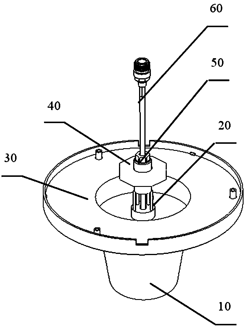
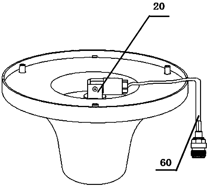
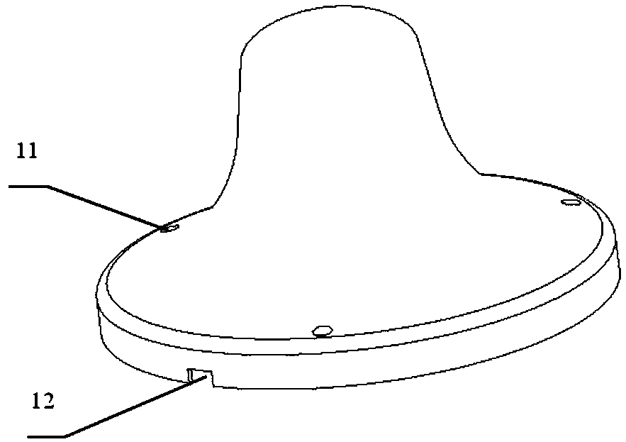
[0041] A room ceiling ceiling antenna, comprising: a radome, a mounting stud rotation mechanism, a bottom plate, a mounting nut plate, a plunger, and a cable;

[0042] The mounting stud rotation mechanism is in a straight line or bent state;

[0043] The installation stud rotation mechanism is connected to the bottom plate, and the bottom plate is clamped with the radome; the plunger is screwed into the installation stud rotation mechanism to fix the cable; the installation The nut plate is used to fix the antenna to the ceiling.

[0044] This application provid...


PUM


Abstract

The present invention belongs to the field of indoor distribution antennas, and discloses an indoor distribution ceiling antenna and an installation method thereof. The antenna comprises a radome, aninstallation stud rotary mechanism, a base plate, an installation nut plate, a plunger and a cable. The installation stud rotary mechanism is in linear or bending state, and is connected with the baseplate, and the base plate is clamped with the radome; the plunger is screwed into the installation stud rotary mechanism to fix the cable; and the installation nut plate is configured to fix the antenna onto a ceiling. The method comprises the steps of: when a soft ceiling installation method is employed, the installation stud rotary mechanism maintains a straight line, the cable and the installation stud rotary mechanism pass through installation holes of the ceiling to fasten, fix and install the nut plate; and when a hard ceiling installation method is employed, the installation stud rotary mechanism is bent and is arranged on the base plate, the cable passes through the radome, and the antenna is fixed on a hard ceiling through a screw. The problem is solved that the application installation environment of an indoor distribution ceiling antenna is single in the prior art, and the indoor distribution ceiling antenna and the installation method thereof are suitable for various installation environments, and are simple in structure and convenient to operate.

Description

technical field [0001] The invention relates to the technical field of indoor antennas, in particular to an indoor ceiling antenna and an installation method thereof. Background technique [0002] Indoor ceiling antennas are generally used for soft ceiling installation, that is, the cables and installation studs pass through the ceiling installation holes and then tightened with installation nut plates. This method is relatively simple. Once the room is hard ceiling, it is not easy to drill holes. If the installation or ceiling installation hole is too large, it cannot be fixed with the installation nut plate, which will bring great inconvenience to the project, affect the progress of the project, and cause losses. Contents of the invention [0003] The embodiment of the present application solves the problem in the prior art that the room-mounted ceiling antenna is applicable to a single installation environment by providing a room-mounted ceiling antenna and an installat...

Claims


Application Information

Patent Timeline
IPC IPC(8): H01Q1/12H01Q1/42H01Q1/00
CPCH01Q1/007H01Q1/1221H01Q1/42
Inventor 胡成军
Owner WUHAN HONGXIN TELECOMM TECH CO LTD
Why Eureka
Try Eureka