Tube bundle for radiant heat transfer by extracting phase transformation heat of compressed steam

A technology of radiation heat transfer and phase change heat, which is applied in heating devices and heating fields, can solve the problems of high pipeline cost, difficult to guarantee construction quality, and increased cost, so as to reduce the difficulty of on-site construction, save the installation workload, and ensure the The effect of engineering quality

Inactive Publication Date: 2012-10-10
陈万仁
View PDF10 Cites 4 Cited by
  • Summary
  • Abstract
  • Description
  • Claims
  • Application Information

AI Technical Summary

Problems solved by technology

[0004] In the above-mentioned technologies, the use of heat pipes or on-site construction to connect the capillary network system can solve the problem of normal operation. However, the high cost of heat pipes has a certain impact on large-scale promotion; The small capillary network can solve the problem that the compressed medium circulation system is too large, and at the same time avoid a series of problems such as high pipeline cost, large filling volume of compressed medium, increased cost, difficult distribution of compressed medium, and poor operation stability. The on-site installation of the pipeline network is difficult, the construction quality is difficult to guarantee, and the construction speed is difficult to meet the actual construction progress.

Method used


Image

  • Tube bundle for radiant heat transfer by extracting phase transformation heat of compressed steam
  • Tube bundle for radiant heat transfer by extracting phase transformation heat of compressed steam
  • Tube bundle for radiant heat transfer by extracting phase transformation heat of compressed steam

Examples


Embodiment 1

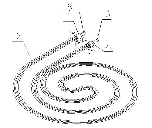
[0021] Embodiment 1: as figure 1 , 2 , 3, and 9, the present embodiment is used to extract the phase change heat of compressed steam for radiation heat transfer. The liquid head 4; the gas distribution head 1 has an air inlet joint 5 installed with it and communicated with the inner cavity, and the liquid return head 4 has a liquid return joint 3 installed with it and communicated with the inner cavity.

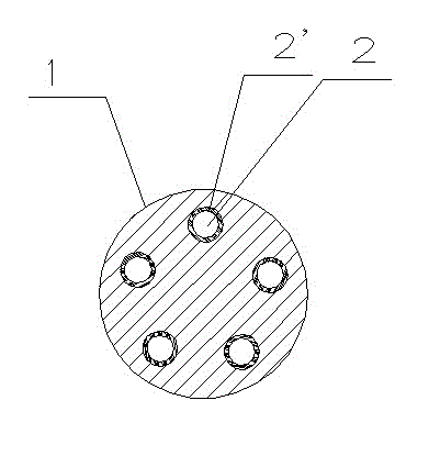
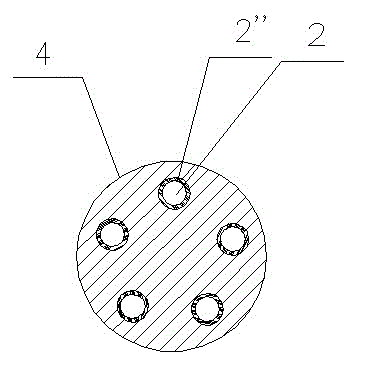
[0022] The structure of the gas distribution head is the same as that of the liquid return head. There are through-holes 2' having the same number as the number of capillary tubes 2 in the distributor head 1. The inner diameters of the through-holes 2' correspond to the outer diameters of each capillary tube 2, and one end of each capillary tube 2 is fixed on the In the through hole 2' in the gas distribution head 1. There are also through-holes 2" in the liquid return head 4 having the same number as the capillary tubes 2, and the inner diameters of the through-holes 2" a...

Embodiment 2

[0025] Embodiment 2: as Figure 4 As shown, the structure of this embodiment is the same as that of Embodiment 1, except that the gas distribution head 1 and the liquid return head 4 are tubes with a length less than or equal to 30 cm, and the inside of the tubes is a stepped hole. One end of each capillary 2 is fixed in the trachea 1 . The other end of each capillary 2 is fixed in the liquid return pipe 4 . The capillaries 2 are evenly distributed in the gas distribution pipe 1 and the liquid return pipe 4 . The ends of the gas distribution pipe 1 and the liquid return pipe 4 all have a bottom plate 6 that fixes the capillary and prevents air leakage.

[0026] Other structures are the same as in Embodiment 1.

Embodiment 3

[0027] Embodiment 3: as Figure 5 , 6 As shown, a group of tube bundles in this embodiment includes 4 capillaries 2, a gas distribution head 1, and a liquid return head 4; the gas distribution head 1 has an air inlet joint 5 installed together with it and communicated with the inner cavity , the liquid return head 4 has a liquid return joint 3 installed together with it and communicated with the inner cavity. The outer diameter of the upper part 1a of the gas distribution head 1 is smaller than the outer diameter of the lower part 1b, and there are 4 through holes 2' communicating with the inner hole of the upper part 1a of the gas distribution head 1 on the bottom surface of the lower part 1b, and each through hole 2' is fixed with a root capillary; in order to facilitate the positioning of the capillary, the through hole 2' can also be a step hole; the inner diameter of the contact part with the air inlet joint 5 is closely matched with the air inlet joint 5, and the length...


PUM


Abstract

A tube bundle for radiant heat transfer by extracting phase transformation heat of compressed steam is characterized in that each tube bundle comprises an air distribution head, a liquid return head and at least two capillary tubes, the air distribution head is provided with an air inlet joint, the air inlet joint and the air distribution head are mounted together, an inner cavity of the air distribution head is communicated with that of the air inlet joint, the liquid return head is provided with a liquid return joint, the liquid return joint and the liquid return head are mounted together, an inner cavity of the liquid return head is communicated with that of the liquid return joint, one end of each capillary tube is fixedly mounted in the air distribution head, and the other end of each capillary tube is fixedly mounted in the liquid return head. The tube bundle can be shaped, processed and produced in a factory or on a construction site, standard construction and installation are performed on a usage site according to a standard process, huge installation workload on the construction site and high heat medium filling quantity are omitted, materials are saved, installation quality and speed are improved, the efficiency is greatly increased, and popularization of compressed steam laying heating technology is guaranteed in terms of product and construction process.

Description

technical field [0001] The invention relates to a heating and heating device which adopts phase change heat extracted from compressed steam for radiation heat transfer. Background technique [0002] At present, with the rapid development of technological innovation and manufacturing technology, in the field of heat pump compressors, frequency conversion and digital scroll compressors have come out, which can operate stably at outdoor temperatures below -25°C and have a high operating energy efficiency ratio. It opens up a new way for the use of air source heat pump in the heating field. In recent years, people have adopted large-scale water source heat pump systems to solve heating and cooling problems. However, due to the limitation of geological conditions in most areas of my country, the stock of groundwater is limited, and the pumped groundwater is difficult to recharge. The application of large water source heat pumps is greatly restricted. Therefore, large water source...

Claims


Application Information

Patent Timeline
Patent Type & Authority Applications(China)
IPC IPC(8): F28D15/04F24D19/00
Inventor 陈万仁梁年良段建磊刘中敏何欣
Owner 陈万仁
Why Eureka
Try Eureka