
Pressure transmitter circuit

A transmission circuit and pressure technology, applied in the field of pressure transmitter circuits, can solve problems such as poor anti-interference performance and poor stability, achieve filtering power frequency interference, enhance anti-interference performance and stability, and have a simple structure Effect

Pending Publication Date: 2018-07-03
上海朝辉压力仪器有限公司
View PDF0 Cites 0 Cited by
  • Summary
  • Abstract
  • Description
  • Claims
  • Application Information

AI Technical Summary

Problems solved by technology

[0003] The technical problem to be solved by the present invention is to provide a pressure transmitter circuit in order to overcome the defects of poor anti-interference performance and poor stability of the pressure transmitter circuit in the prior art

Method used


Image

  • Pressure transmitter circuit

Examples


Embodiment Construction

[0024] The present invention is further illustrated below by means of examples, but the present invention is not limited to the scope of the examples.

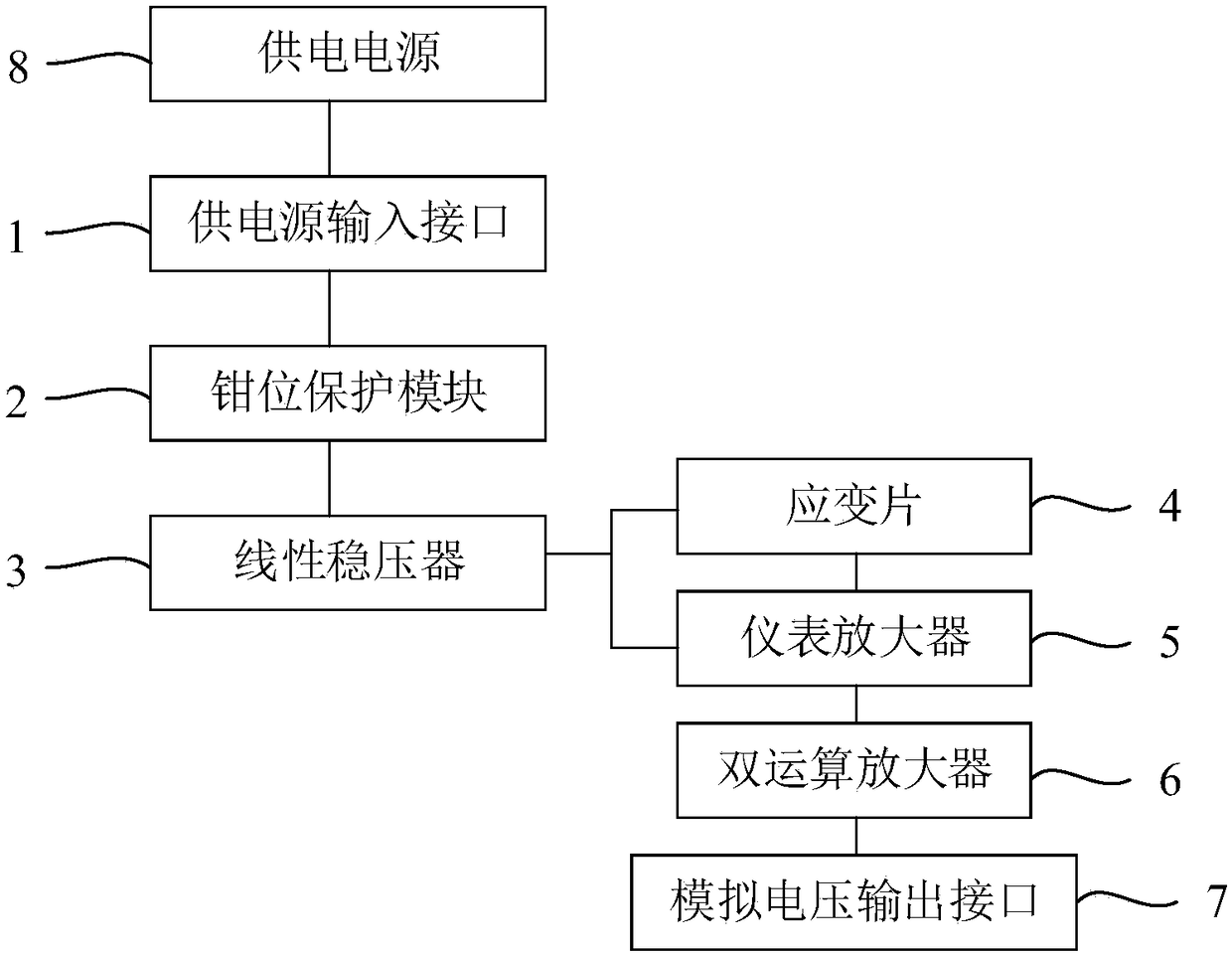
[0025] The pressure transmission circuit of this embodiment includes a power supply input interface 1 , a clamp protection module 2 , a linear voltage regulator 3 , a strain gauge 4 , an instrument amplifier 5 , a dual operational amplifier 6 and an analog voltage output interface 7 . The input terminal of the clamp protection module is electrically connected to the input interface of the power supply 8, the output terminal of the clamp protection module 2 is electrically connected to the power supply terminal of the strain gauge 4 through the linear voltage regulator 3, and the output terminal of the strain gauge 4 is amplified by the instrument 5 It is electrically connected with the dual operational amplifier 6 and the analog voltage output interface 7, and the strain gauge is attached to an elastic body (a polymer material ...


PUM

PropertyMeasurementUnit
Capacitanceaaaaaaaaaa

Abstract

The invention discloses a pressure transmitter circuit comprising a clamping protection module, a linear voltage regulator and a strain gauge. The input terminal of the clamping protection module is connected with a power supply electrically and the output terminal of the clamping protection module is connected with a power supply terminal of the strain gauge electrically through the linear voltage regulator. The clamping protection module is used for carrying out amplitude-limiting and filtering on an input voltage of the power supply and transmitting the processed voltage to the linear voltage regulator. The linear voltage regulator is used for carrying out voltage stabilization on the inputted voltage and transmitting the processed voltage to the strain gauge. According to the invention, the clamping protection module is able to carry out amplitude-limiting and filtering on the inputted voltage that is transmitted to the pressure transmitter circuit by a distribution line to filterinstantaneous large voltages and currents, so that the pulse interference of the inputted voltage is eliminated and thus the power frequency interference generated by coupling of the distribution lineand the pressure signal transmission line is greatly filtered. Therefore, the anti-interference performance and stability of the circuit are enhanced. Moreover, the pressure transmitter circuit has asimple structure.

Description

technical field [0001] The invention relates to a pressure transmitter circuit. Background technique [0002] In the process of industrial production and manufacturing, pressure transmitters are commonly used to measure the liquid level, density and pressure of liquids, gases or vapors, and to supply secondary instruments or control systems such as indicating alarms, recorders, regulators, etc. for measurement, indication and process adjustment. . During the working process of the pressure transmitter, due to the coupling between the distribution line of the pressure transmitter and the adjacent pressure signal transmission line, it is easy to generate power frequency interference, and the existence of the above interference will affect the accuracy of data acquisition and data Transmission stability. Although there are anti-jamming protection circuits in the prior art, they all have the defects of poor anti-jamming performance and poor stability. Contents of the inventi...

Claims


Application Information

Patent Timeline
IPC IPC(8): H02H9/04H02H9/02
CPCH02H9/02H02H9/04
Inventor 伍正辉李慧
Owner 上海朝辉压力仪器有限公司
Learn More