
Bridge equipment

A technology for equipment and bridges, applied in the field of bridge equipment, can solve the problems of low production efficiency, complex operation, waste of manpower, etc., and achieve the effect of reducing manpower, simple operation, and reducing processing time.

Inactive Publication Date: 2018-07-06
ANHUI WEIHONG STEEL STRUCTURE GRP
View PDF8 Cites 4 Cited by
  • Summary
  • Abstract
  • Description
  • Claims
  • Application Information

AI Technical Summary

Problems solved by technology

[0002] In the process of bridge construction, a large number of steel plates and steel materials are needed. According to different needs of the actual situation, the steel plates and steel materials are processed. During the processing, the staff need to grind and drill the steel plates and steel materials according to the requirements. Drilling equipment and grinding equipment are needed when drilling. When grinding and drilling of steel plates are required, since drilling and grinding are carried out on different machines, it is often necessary to place the steel plate on the drilling equipment and grinding equipment. When switching between devices, the steel plate needs to be clamped and positioned multiple times. The operation is complicated, time-consuming and labor-intensive, resulting in unnecessary waste of manpower and low production efficiency.

Method used


Image

  • Bridge equipment
  • Bridge equipment

Examples


Embodiment Construction

[0017] The following will clearly and completely describe the technical solutions in the embodiments of the present invention with reference to the accompanying drawings in the embodiments of the present invention. Obviously, the described embodiments are only some, not all, embodiments of the present invention. Based on the embodiments of the present invention, all other embodiments obtained by persons of ordinary skill in the art without making creative efforts belong to the protection scope of the present invention.

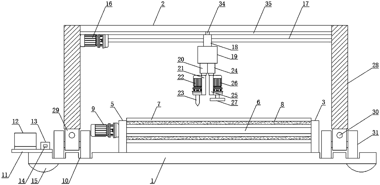
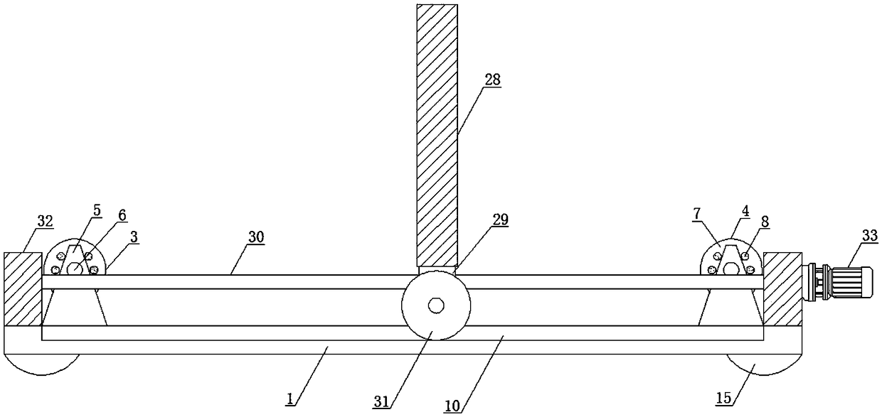
[0018] according to figure 1 In the shown bridge equipment, the crossbeam 2 is arranged on the top of the bottom plate 1, the first bearing mechanism 3 and the second bearing mechanism 4 both include support plates 5, and rotating rods 6 are arranged between the support plates 5, The rotating rod 6 runs through the support plate 5 and is connected to the transmission motor 9. The outer side of the rotating rod 6 is provided with a bearing roller 7, and the bea...


PUM


Abstract

The invention discloses bridge equipment. The bridge equipment comprises a base plate and a cross beam; the cross beam is arranged at the top of the base plate; a first bearing mechanism and a secondbearing mechanism are arranged at the top of the base plate; the second bearing mechanism is arranged on one side of the first bearing mechanism; the first bearing mechanism and the second bearing mechanism both comprise support plates; rotating rods are arranged between the support plates; bearing rollers are arranged on the outer sides of the rotating rods; multiple electromagnets are arranged in the bearing rollers; conveying motors are arranged on the side surfaces of the support plates; movable grooves are formed in the two sides of the first bearing mechanism; bearing plates are arrangedon one sides of the movable grooves; and mobile terminals and control cabinets are arranged at the tops of the bearing plates. A drilling cutter or a grinding cutter moves to a proper position, and the drilling cutter is continuously rotated and descended or the grinding cutter is rotated, so that steel plates or steel materials are punched or grinded; and the bridge equipment is reasonable in design, convenient to operate and use and high in automation degree, and reduces labors.

Description

technical field [0001] The invention relates to the technical field of bridges, in particular to bridge equipment. Background technique [0002] In the process of bridge construction, a large number of steel plates and steel materials are needed. According to different needs of the actual situation, the steel plates and steel materials are processed. During the processing, the staff need to grind and drill the steel plates and steel materials according to the requirements. Drilling equipment and grinding equipment are needed when drilling. When grinding and drilling of steel plates are required, since drilling and grinding are carried out on different machines, it is often necessary to place the steel plate on the drilling equipment and grinding equipment. When switching between devices, the steel plate needs to be clamped and positioned multiple times. The operation is complicated, time-consuming and labor-intensive, resulting in unnecessary waste of manpower, and at the sa...

Claims


Application Information

Patent Timeline
IPC IPC(8): B23P23/04B23Q3/154B23Q5/40
CPCB23P23/04B23Q3/1543B23Q5/40
Inventor 曹雁冰
Owner ANHUI WEIHONG STEEL STRUCTURE GRP
Learn More