Injection mold with direct-ejecting sprue forcible-disengaging structure

A technology of injection mold and straight ejection, which is applied to household appliances, other household appliances, and household components, etc. It can solve the problems that finished parts cannot be ejected from the movable mold, and achieve the effect of fast filling and high molding quality

Pending Publication Date: 2018-07-06
青岛海泰科模具有限公司
View PDF0 Cites 0 Cited by
  • Summary
  • Abstract
  • Description
  • Claims
  • Application Information

AI Technical Summary

Problems solved by technology

[0003] In view of the deficiencies of the above-mentioned prior art, the purpose of the present invention is to propose an injection mold with a straight-top gate strong release structure to solve the problem that multiple gates feed hot fluid into the injection cavity to ensure that the injection cavity is filled quickly. The material handle formed by the gate is connected to the product part, resulting in the problem that the finished part cannot be ejected from the movable mold

Method used


Image

  • Injection mold with direct-ejecting sprue forcible-disengaging structure
  • Injection mold with direct-ejecting sprue forcible-disengaging structure
  • Injection mold with direct-ejecting sprue forcible-disengaging structure

Examples


Embodiment Construction

[0021] The present invention is described in detail below in conjunction with accompanying drawing:

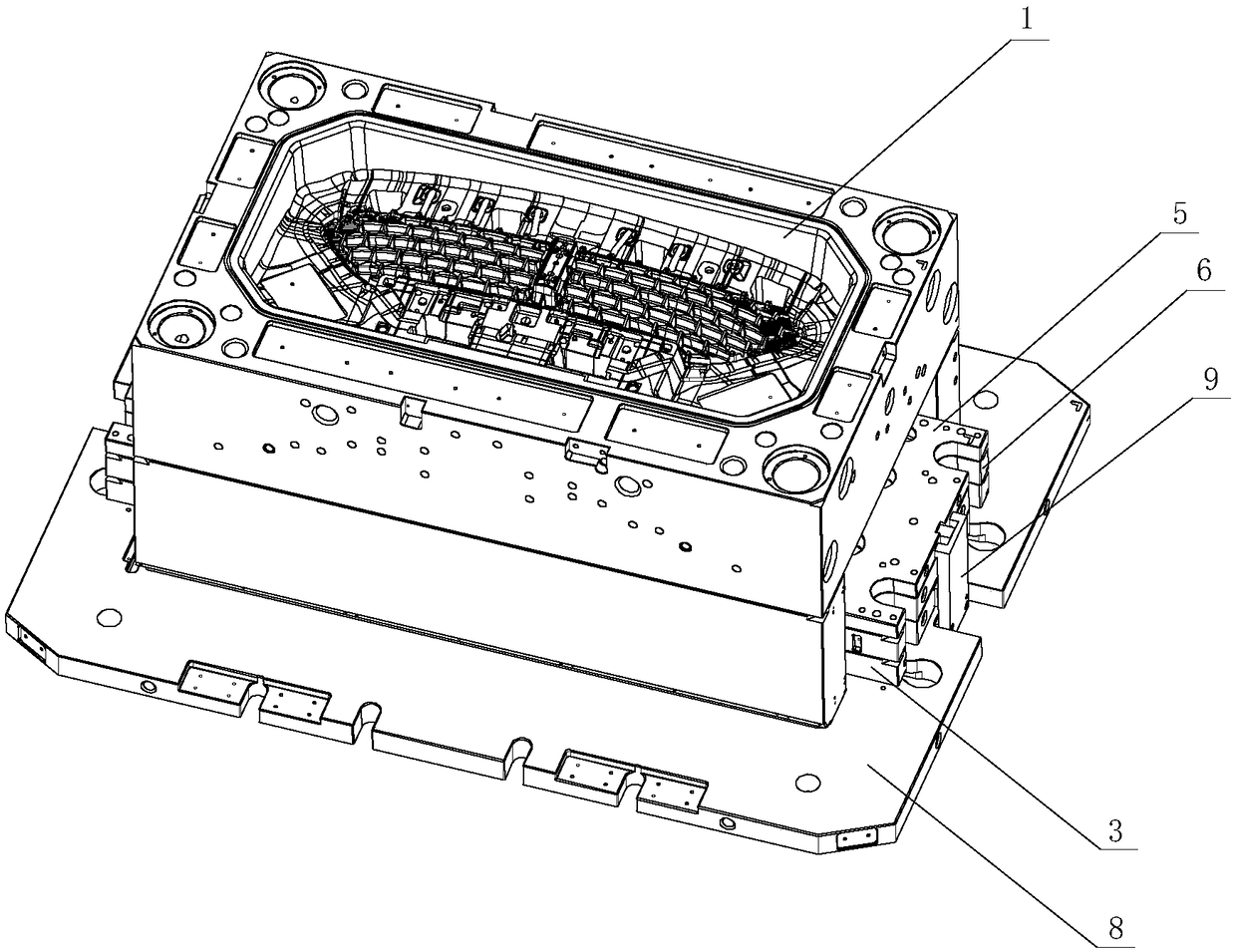
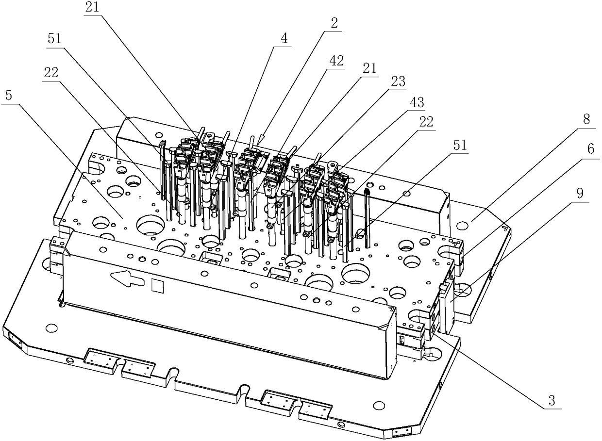
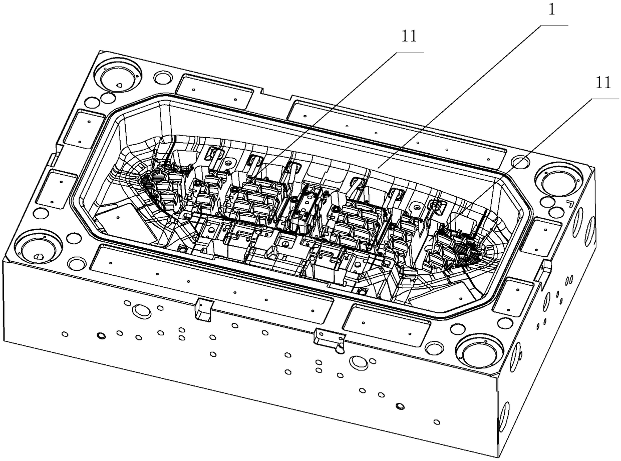
[0022] combine Figure 1 to Figure 6 , an injection mold with a straight top gate strong release structure, including a movable mold 1, a straight top mechanism 2, a secondary ejector plate 3 and a base 8, and there are six straight top mechanisms 2, and each straight top mechanism 2 both include a straight top 21 and a push rod 22, and the straight top 21 is embedded in the installation position 11 on the upper part of the movable mold 1. There are two ejector rods 22 of each straight ejector mechanism 2, and the two ejector rods 22 are arranged vertically in parallel. 3 are fixedly connected. The outer side of each ejector rod 22 is covered with a sliding sleeve 23, and the sliding sleeve 23 is fixedly connected with the movable mold 1. The ejector rod 22 is slidably matched with the movable mold 1 through the sliding sleeve 23, and the secondary ejector plate 3 passes thr...


PUM


Abstract

The invention discloses an injection mold with a direct-ejecting sprue forcible-disengaging structure. The injection mold with the direct-ejecting sprue forcible-disengaging structure comprises a movable mold body, a plurality of direct ejecting mechanisms, a secondary ejecting plate and a base. Each direct ejecting mechanism comprises a direct ejector and an ejecting rod, wherein the direct ejector is inlaid in a mounting position on the upper portion of the movable mold body. The direct ejectors can be disengaged from the mounting position of the movable mold body by means of the secondary ejecting plate through the ejecting rods. A cavity surface matched with the movable mold body is formed on the upper portion of each direct ejector. A spure is arranged on one side of each direct ejector. An elastic pin is arranged in each direct ejector. One end of each elastic pin faces the corresponding sprue. Each direct ejecting mechanism is provided with an acceleration mechanism. The acceleration mechanisms are matched with the corresponding elastic pins, so that the elastic pins are made to move towards the sprues. The base is located under the secondary ejecting plate. The two sides ofthe base are connected with the secondary ejecting plate through two secondary ejecting mechanisms separately. According to the injection mold with the direct-ejecting sprue forcible-disengaging structure, the sprues are arranged on the direct ejectors, and hot fluid enters an injection cavity from multiple positions, so that mold filling is rapid, and the molding quality is high; and materials in the sprues can be separated from the direct ejectors conveniently, and finally, finished products are smoothly ejected out of the movable mold body.

Description

technical field [0001] The invention relates to the technical field of injection molds, in particular to an injection mold with a straight top gate strong release structure. Background technique [0002] The main body of the ventilation grille of the automobile is made of an injection mold. Since the structural shape of the ventilation grille is densely ribbed and narrow in width, the injection cavity formed after the fixed mold and the movable mold are molded is honeycomb-shaped. In the case of less, the molding cycle is long, the production efficiency is low, and the thermal fluid has solidified before it completely fills the injection cavity, resulting in incomplete molding of the product and resulting in product scrap. Therefore, it is necessary to add multiple gates. In the case of more gates, after the product is formed, the material handle formed in the feed channel is connected with the product piece, resulting in that the product piece cannot be ejected from the mov...

Claims


Application Information

Patent Timeline
Patent Type & Authority Applications(China)
IPC IPC(8): B29C45/26B29C45/27B29C45/38B29C45/40B29L31/14
CPCB29C45/26B29C45/27B29C45/38B29C45/4005B29L2031/14
Inventor 郭峰孙文强王纪学王洪波
Owner 青岛海泰科模具有限公司
Why Eureka
Try Eureka