
A Networked Radar Antenna Configuration Method Combining State Prediction and Particle Swarm Optimization

An antenna configuration and networking radar technology, applied in the radar field, can solve problems such as reducing the amount of calculation

Active Publication Date: 2021-10-26
UNIV OF ELECTRONICS SCI & TECH OF CHINA
View PDF9 Cites 0 Cited by
  • Summary
  • Abstract
  • Description
  • Claims
  • Application Information

AI Technical Summary

Problems solved by technology

For the former change, it is indeed a feasible method to completely recalculate each time, but for the second one, recalculation will ignore the laws between environments, which may have a great effect in reducing the amount of calculations. effect

Method used


Image

  • A Networked Radar Antenna Configuration Method Combining State Prediction and Particle Swarm Optimization
  • A Networked Radar Antenna Configuration Method Combining State Prediction and Particle Swarm Optimization
  • A Networked Radar Antenna Configuration Method Combining State Prediction and Particle Swarm Optimization

Examples


Embodiment Construction

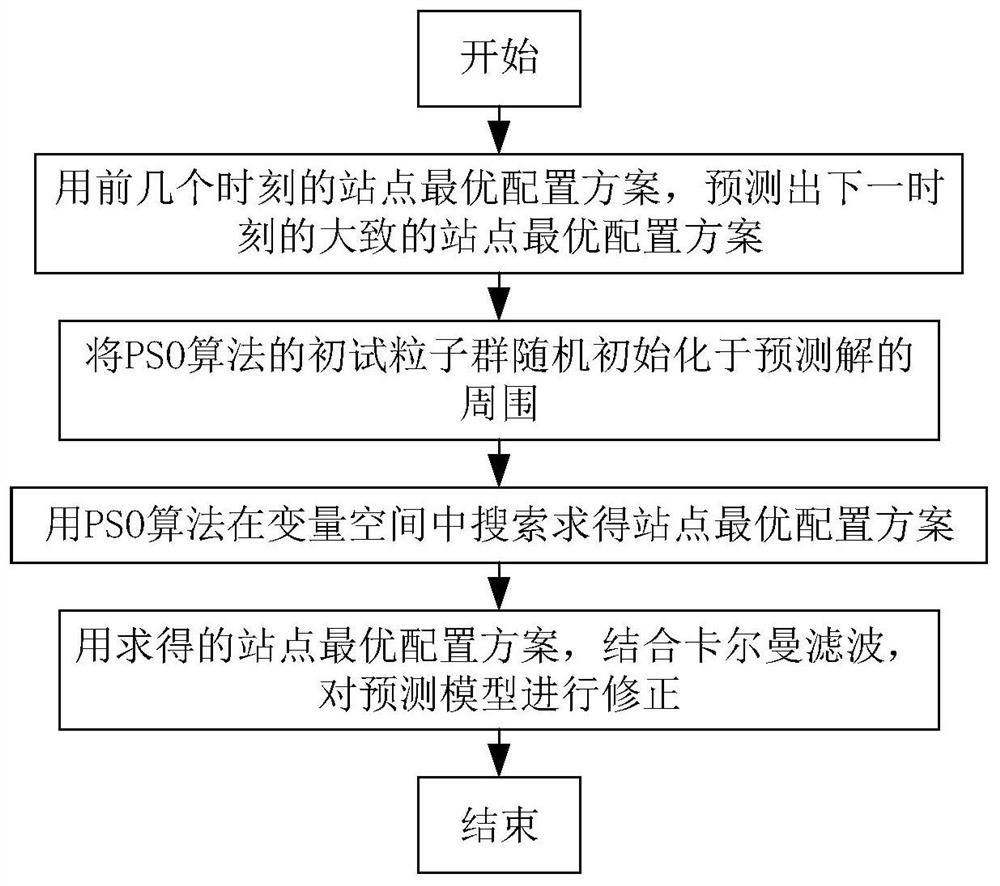
[0049]The technical scheme adopted in the present invention is based on networking radar, using Kalman filter and multi-objective PSO algorithm, while effectively optimizing the radar site configuration, it can adaptively terminate the optimization calculation process according to the optimization result, including the following steps:

[0050] For the first three moments, they are regarded as independent of each other, and the optimal site configuration scheme is calculated using the traditional PSO method. Then you can enter the algorithm proposed in this paper:

[0051] S1. Using the prediction model of Kalman filter, according to the previous site optimization configuration plan, predict the approximate site optimization configuration plan at the next moment. The specific operation method is:

[0052] The state vector of the site configuration scheme at the third moment is:

[0053]

[0054] in and are the antenna positions of the optimal site configuration schemes...


PUM


Abstract

The invention discloses a prediction-based networked radar optimization antenna configuration method in a dynamic environment. The method belongs to the field of radar technology, and specifically relates to optimizing the configuration of networked radar sites by using a state prediction-based particle swarm optimization algorithm in a dynamic environment. . In the dynamic battlefield environment, the present invention can predict the approximate position of the radar site at the new time according to the optimal site configuration scheme at the previous moment, and then use the PSO method to obtain the actual optimal site configuration scheme, which can effectively reduce the calculation time and Avoid the waste of computing resources, and quickly obtain the optimal configuration results of radar sites at each moment in a dynamic environment.

Description

technical field [0001] The invention belongs to the field of radar technology, and in particular relates to optimizing the configuration of networked radar sites by using a particle swarm optimization algorithm based on state prediction in a dynamic environment. Background technique [0002] With the development of integrated electronic warfare, traditional radars working alone cannot complete multiple tasks, and their own survival has become an urgent problem to be solved, and a single radar cannot compete with electronic countermeasures systems. In this case, the multi-function radar network emerges as the times require. Relevant experts of the U.S. Air Force and Army generally believe that networking is the most promising anti-stealth and anti-jamming approach. The U.S. Army has concentrated its efforts on prioritizing the networking work to improve its surveillance and combat capabilities, and has studied the continuous improvement and perfection of the mature intellige...

Claims


Application Information

Patent Timeline
Patent Type & Authority Patents(China)
IPC IPC(8): G06Q10/04G06N3/00
CPCG06N3/006G06Q10/04
Inventor 张天贤汪子钦王远航时巧崔国龙孔令讲杨晓波易伟
Owner UNIV OF ELECTRONICS SCI & TECH OF CHINA
Learn More