Hand protecting fence for stamping apparatus

A technology for hand protection and stamping equipment, applied in the stamping field, can solve the problems of aging and failure of components and difficult to detect, and achieve the effects of low production cost, avoidance of work-related injuries and convenient installation.

Inactive Publication Date: 2018-07-10
陈彩云
View PDF11 Cites 6 Cited by
  • Summary
  • Abstract
  • Description
  • Claims
  • Application Information

AI Technical Summary

Benefits of technology

This innovation makes it easier than traditional methods by creating an easy-to use machine with fewer parts while still providing its functionality at least three times longer. It uses a mechanism called a linking system where two rods connect together through a pivot joint. A pin extends between these rod ends when they reach their maximum length during each cycle or after being pressed into place. By moving back and forth along this line, there will also cause another part connected to both rods to shift up/down slightly within 33% of every other strokes. These movements help prevent injury if someone tries to touch them accidentally.

Problems solved by technology

This patented technical problem addressed in this patents relates to improving upon existing methods used during production processes where workers use tools while working near dangerous areas (such as when they shouldn't touch them). These conventional ways involve light curtains or starting up an alarm system before getting hurt from heavy machinery. However, none offer effective solutions due to their limitations - either too expensive or lacked durability over time.

Method used


Image

  • Hand protecting fence for stamping apparatus
  • Hand protecting fence for stamping apparatus

Examples


Embodiment Construction

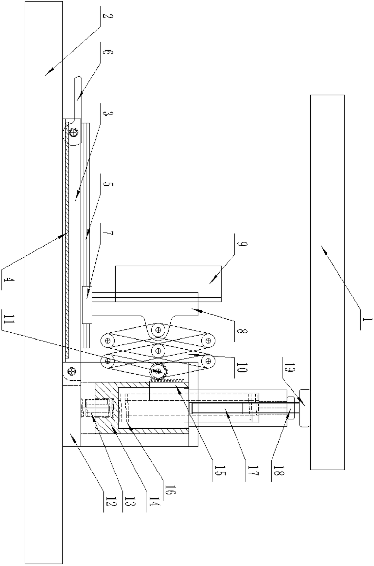
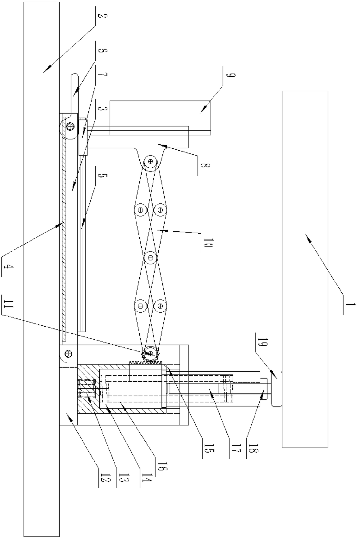
[0013] Such as figure 1 with figure 2 As shown, this specific embodiment adopts the following technical solutions: a hand protection bar for stamping equipment, including a sliding seat 1 on the punching machine and a lower working surface 2 on the punching machine, the sliding seat 1 on the punching machine is located above the lower working surface 2 of the punching machine, Also includes base 3, powerful magnet 4, slide rail 5, disassembly handle 6, slider 7, slide plate 8, push hand plate 9, telescopic arm 10, gear 11, recessed seat 12, small spring 13, movable block 14, rack 15. Large spring 16, bolt 17, adjusting nut 18 and support seat 19; the lower surface of the base 3 is fixedly connected with a powerful magnet 4; the base 3 is fixedly connected to the upper surface of the lower working table 2 of the punch press through the powerful magnet 4 The left side of the upper surface of the lower working table 2 of the punch press is fixedly connected with a concave word ...


PUM


Abstract

The invention discloses a hand protecting fence for a stamping apparatus. The hand protecting fence for the stamping apparatus has the advantages of being reasonable and simple in structure, low in production cost, convenient to install and complete in function. According to the hand protecting fence for the stamping apparatus, transverse movement is generated by using the lengthways movement of astamping machine, and the hands can be forcibly removed out of the working range of a die within the distance of one third of the total travel according to the linkage principle of a mechanical structure, so that the personal safety of an operator is guaranteed. When the upper sliding seat of the stamping machine goes downwards, a bolt moves downwards to drive a rack to move downwards, the rack drives a gear to rotate, a telescopic arm is driven by the gear to unfold, a sliding block slides leftwards on a sliding rail so that a hand pushing plate pushes the hands of the operator away from theposition between the upper sliding seat of the stamping machine and a lower workbench surface of the stamping machine, the operator is protected, and occupational injury is avoided.

Description


Claims


Application Information

Patent Timeline
Owner 陈彩云
Why Eureka
Try Eureka