Powder laying mechanism of 3D printer of fan-shaped structure

A 3D printer and fan-shaped structure technology, which is applied in the field of 3D printing, can solve the problems of metal powder use waste, etc., and achieve the effect of reducing usage and reducing production costs

Active Publication Date: 2018-07-10
ANHUI TECHN COLLEGE OF MECHANICAL & ELECTRICAL ENG
View PDF11 Cites 2 Cited by
  • Summary
  • Abstract
  • Description
  • Claims
  • Application Information

AI Technical Summary

Problems solved by technology

[0003] 3D printing is usually realized by using digital technology material printers. It is often used to manufacture models in the fields of mold manufacturing and industrial design, and is gradually used in the direct manufacturing of some products. It has been applied in many fields. Now Most of the powder spreading mechanisms with printing equipment are in the form of horizontal sliding movement. Each time the powder is spread, the entire printing platform is covered. No matter the size of the printed object, the same amount of metal powder is required, so that most of the metal powder does not Doesn't work, it's wasteful to use metal powder

Method used


Image

  • Powder laying mechanism of 3D printer of fan-shaped structure
  • Powder laying mechanism of 3D printer of fan-shaped structure
  • Powder laying mechanism of 3D printer of fan-shaped structure

Examples


Embodiment Construction

[0028] Below in conjunction with accompanying drawing and embodiment of description, specific embodiment of the present invention is described in further detail:

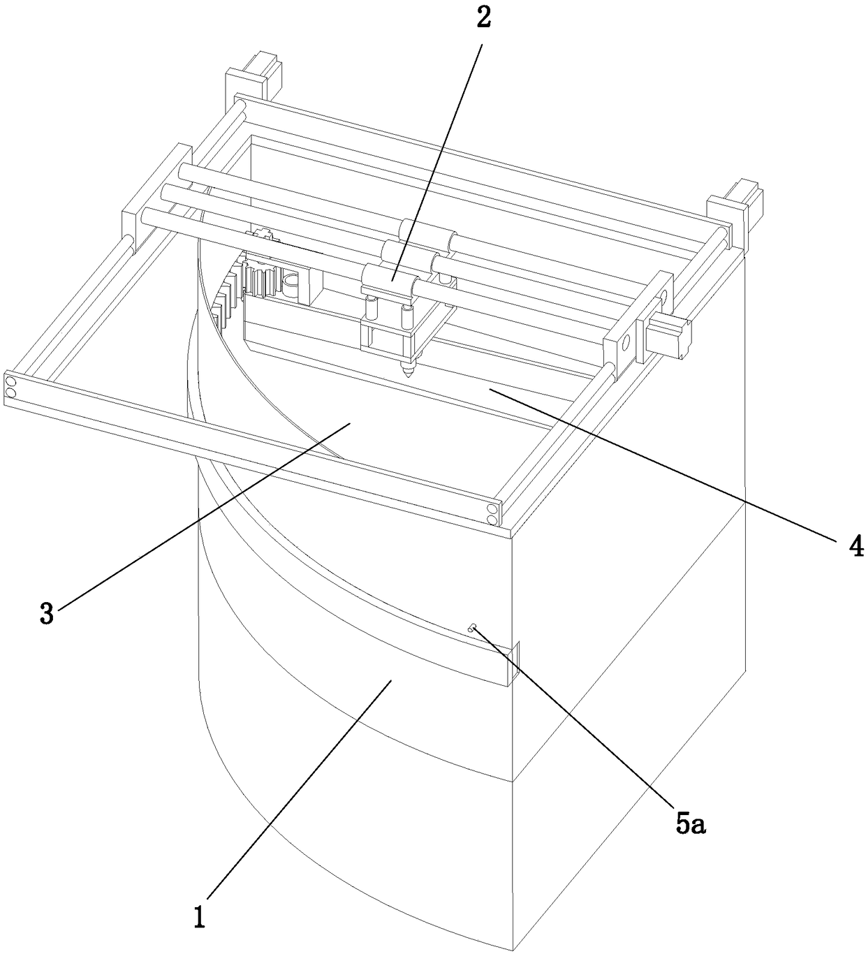
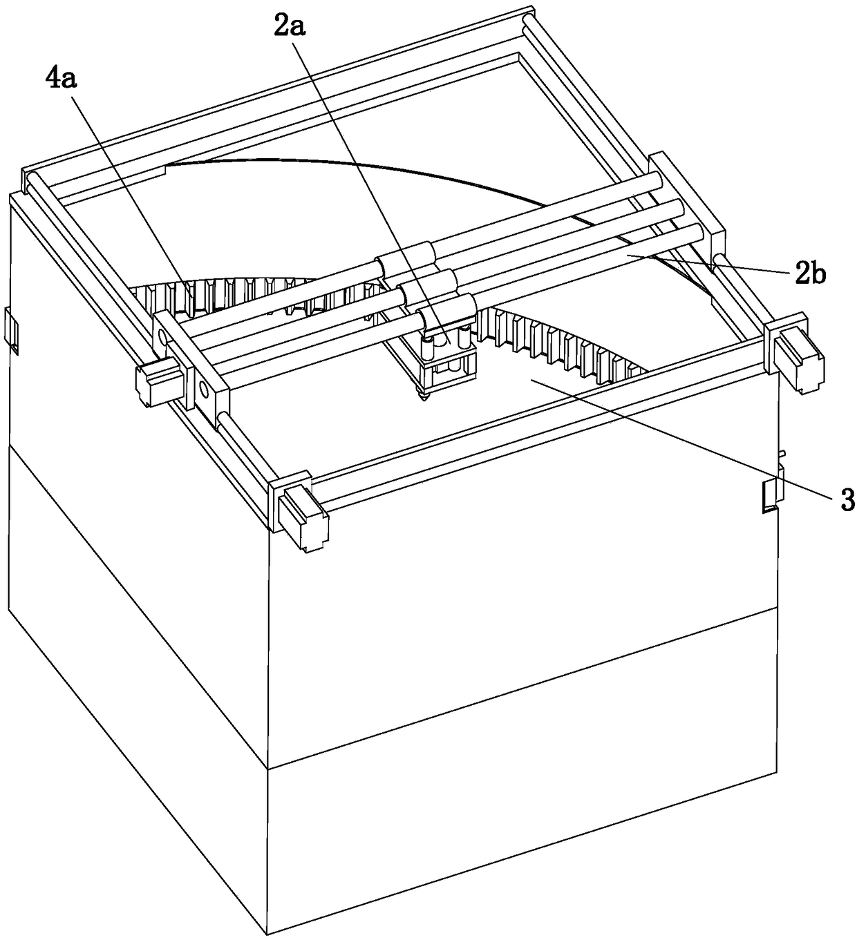
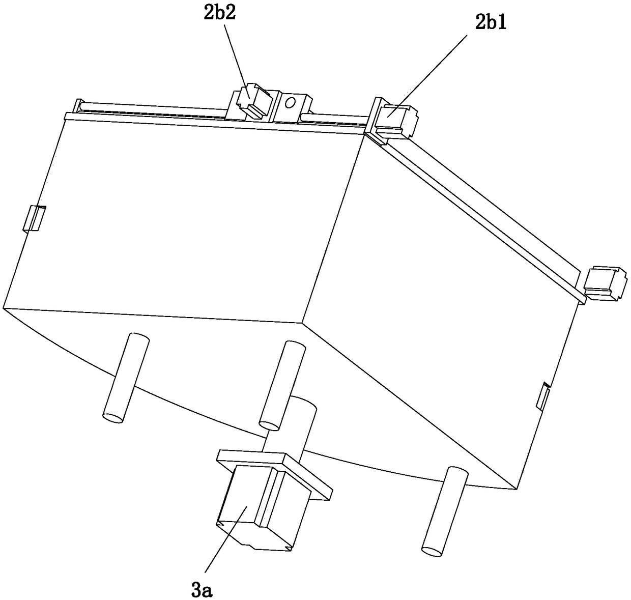
[0029] refer to Figure 1 to Figure 12 A fan-shaped 3D printer is shown, including a fan-shaped housing 1 with a horizontal section, a laser burning device 2 arranged on the top of the housing 1, a lifting platform 3 arranged in the housing 1, and a powder spreading mechanism 4 and a control device, the laser burning device 2 includes a laser burning mechanism 2a and a first driving mechanism 2b for driving the translation of the laser burning mechanism 2a, and the powder spreading mechanism 4 is arranged directly above the lifting platform 3, The lifting platform 3 is horizontally arranged and has a fan-shaped structure. The powder spreading mechanism 4 includes a powder falling mechanism 4a and a second drive mechanism 4b for driving the powder falling mechanism 4a to rotate. The bottom of the lifting platform 3 i...


PUM


Abstract

The invention relates to the technical field of 3D printing, in particular to a powder laying mechanism of a 3D printer of a fan-shaped structure. The powder laying mechanism comprises a powder falling mechanism, a second driving mechanism and a control device, wherein the second driving mechanism is used for driving the powder falling mechanism to rotate; the control device comprises a controllerand a sensor assembly electrically connected with the controller; the powder falling mechanism comprises a material carrying assembly used for carrying materials and a limitation assembly used for limiting the material falling quantity; the second driving mechanism comprises a circular arc-shaped inner gear ring and an engagement assembly engaged with the inner gear ring; the limitation assemblyis arranged in the material carrying assembly; the engagement assembly is fixedly arranged on the material carrying assembly; the engagement assembly, the material carrying assembly and the limitationassembly are all electrically connected with the controller. The powder laying structure is in the fan shape; the casing is of the fan-shaped structure; the consumption of metal powder during articleprinting in each time can be reduced; the production cost is reduced.

Description

technical field [0001] The invention relates to the technical field of 3D printing, in particular to a powder spreading mechanism of a fan-shaped 3D printer. Background technique [0002] 3D printing is a kind of rapid prototyping technology. It is a technology based on digital model files and using bondable materials such as powdered metal or plastic to construct objects by layer-by-layer printing. [0003] 3D printing is usually realized by using digital technology material printers. It is often used to manufacture models in the fields of mold manufacturing and industrial design, and is gradually used in the direct manufacturing of some products. It has been applied in many fields. Now Most of the powder spreading mechanisms with printing equipment are in the form of horizontal sliding movement. Each time the powder is spread, the entire printing platform is covered. Regardless of the size of the printed object, the same amount of metal powder is required, so that most of ...

Claims


Application Information

Patent Timeline
Patent Type & Authority Applications(China)
IPC IPC(8): B22F3/105B33Y30/00
CPCB22F3/003B33Y30/00B22F10/00B22F12/222B22F12/46B22F12/226B22F12/90B22F12/52B22F10/30B22F10/20B22F12/30B22F12/224Y02P10/25
Inventor 王甫段贤勇张新建牛莉张成林
Owner ANHUI TECHN COLLEGE OF MECHANICAL & ELECTRICAL ENG
Why Eureka
Try Eureka