Fixing device for plastic pipes for bridge

A technology for fixing devices and plastic pipes, which is applied in the direction of pipe brackets, pipes/pipe joints/fittings, mechanical equipment, etc., which can solve problems affecting the convenience and reliability of operation, applicability and practical limitations, and achieve convenient maintenance and Change the position, ensure the stability and reliability of the installation, and the effect of strong applicability

Inactive Publication Date: 2018-07-10
王恒标
View PDF0 Cites 0 Cited by
  • Summary
  • Abstract
  • Description
  • Claims
  • Application Information

AI Technical Summary

Problems solved by technology

[0002] On some bridges, we can often see large and small plastic pipes, which are mainly used for drainage or wiring. Since the plastic pipes are long and have a large gravity, in order to ensure their stability, they need to be installed on the bridge wall. The support structure is used to support it and prevent it from sinking or falling. In the prior art, it is generally realized by screwing the support structure on the bridge wall. Although the use of screw fixing can realize the installation and positioning of the support structure, in practical applications During the process, maintenance or displacement is sometimes required, but the support structure of traditional technology cannot be operated at all, which will seriously affect the convenience and reliability of its operation, so the applicability and practicability are limited

Method used


Image

  • Fixing device for plastic pipes for bridge

Examples


Embodiment 1

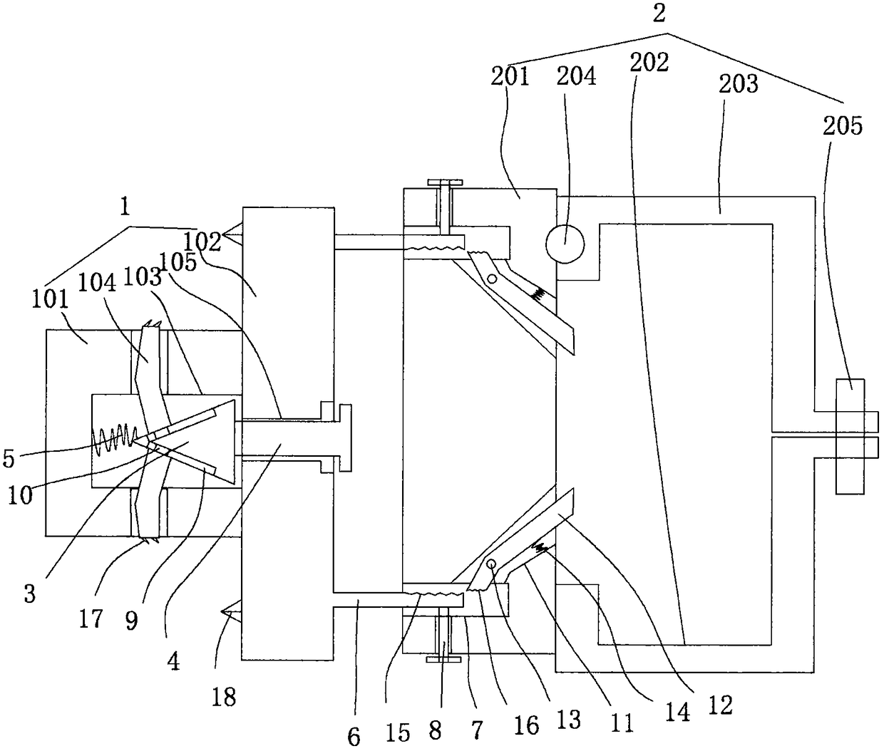
[0015] figure 1 A specific embodiment of the present invention is shown, wherein figure 1 It is a schematic diagram of the structure of the present invention.

[0016] see figure 1 , A plastic pipe fixing device for a bridge, comprising a mounting base 1 and a fixing structure 2 arranged on the mounting base 1. The mounting base 1 includes a plug-in column 101 and a pressure panel fixed on the outer end of the plug-in column 101 102. A cavity 103 is provided in the plug-in cylinder 101, and a pressing tooth 104 communicating with the cavity 103 is uniformly fixed on the side wall of the plug-in cylinder 101. The center of the panel 102 is fixed with a screw hole 105 communicating with the cavity 103, a conical abutment block 3 is arranged in the cavity 103, and a screw 4 is arranged in the screw hole 105. The inner end is pressed against the big end of the cone block 3, the inner side of the pressing tooth 104 is pressed against the surface of the cone block 3, and the cone ti...


PUM


Abstract

The invention discloses a fixing device for plastic pipes for a bridge. The fixing device comprises a mounting seat and a fixing structure, wherein the fixing structure is arranged on the mounting seat. The mounting seat comprises an insertion column body and an abutting panel, wherein the abutting panel is fixed to the outer side end of the insertion column body. The insertion column body is internally provided with a cavity. Abutting clamping teeth are uniformly fixed to the side wall of the insertion column body, wherein the abutting clamping teeth communicate with the cavity. A screw holeis fixedly formed in the center of the abutting panel, wherein the screw hole communicates with the cavity. The cavity is internally provided with a conical abutting block. The screw hole is internally provided with a screw rod. Column bodies are uniformly fixed to the outer side face of the abutting panel. The fixing structure comprises a fixing seat, a U-shaped clamping block and an n-shaped buckling block, wherein the U-shaped clamping block and the n-shaped buckling block are arranged on the fixing seat. Insertion holes are fixedly formed in the side face of the fixing seat, wherein the insertion holes are matched with the column bodies. Locking position screw rods are fixed to the side wall of the fixing seat, wherein the locking position screw rods are matched with the insertion holes. The fixing device is reasonable in structural arrangement; the mounting seat can be separated from the fixing structure; it can be guaranteed that the mounting seat is mounted stably and reliably;and the fixing device is convenient and fast to operate, good in use stability and great in adaptability.

Description

Technical field [0001] The invention belongs to the technical field of bridge accessories, and specifically relates to a plastic pipe fixing device for bridges. Background technique [0002] On some bridges, we can often see large and small plastic pipes, which are mainly used for drainage or wiring. Because the plastic pipes are longer and have greater gravity, in order to ensure their stability in use, they need to be installed on the bridge wall. The supporting structure is used to support it and prevent it from sinking or falling. In the prior art, it is generally realized by connecting the supporting structure with threads on the bridge wall. Although the supporting structure can be installed and positioned by screw fixing, it is used in practical applications. In the process, it is sometimes necessary to perform maintenance or displacement, but the support structure of traditional technology cannot be operated at all, which will seriously affect the convenience and reliabil...

Claims


Application Information

Patent Timeline
Patent Type & Authority Applications(China)
IPC IPC(8): F16L3/10
CPCF16L3/10
Inventor 王恒标
Owner 王恒标
Why Eureka
Try Eureka