
Collimating backlight structure, display device thereof, double-screen display device, and multi-screen display device

A technology of backlight structure and multi-screen display, applied in lighting devices, fixed lighting devices, components of lighting devices, etc., can solve the problems of unable to achieve collimated light, affecting the display effect of the display screen, etc., to save space and improve backlight effect of effect

Active Publication Date: 2018-07-10
BOE TECH GRP CO LTD
View PDF7 Cites 1 Cited by
  • Summary
  • Abstract
  • Description
  • Claims
  • Application Information

AI Technical Summary

Problems solved by technology

[0002] The backlight module in the prior art generally includes a base substrate and a shroud arranged on the base substrate. The shroud and the base substrate are surrounded to form a plurality of grooves, each groove is provided with a light source, and each groove There is a controllable light-transmitting structure in the slot of the controllable light-transmitting structure, and a micro-lens is arranged above the controllable light-transmitting structure; the controllable light-transmitting structure includes a light-transmitting area and an adjustable area; The area is light-transmitting, and the light source of the backlight module in the prior art generally cannot achieve collimated light on the display screen, thereby affecting the display effect of the display screen

Method used


Image

  • Collimating backlight structure, display device thereof, double-screen display device, and multi-screen display device
  • Collimating backlight structure, display device thereof, double-screen display device, and multi-screen display device
  • Collimating backlight structure, display device thereof, double-screen display device, and multi-screen display device

Examples


Embodiment Construction

[0026] In order to make the objectives, technical solutions and advantages of the present invention clearer, the embodiments of the present invention will be described in detail below with reference to the accompanying drawings. It should be noted that, the embodiments in the present application and the features in the embodiments may be arbitrarily combined with each other if there is no conflict.

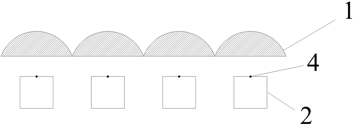
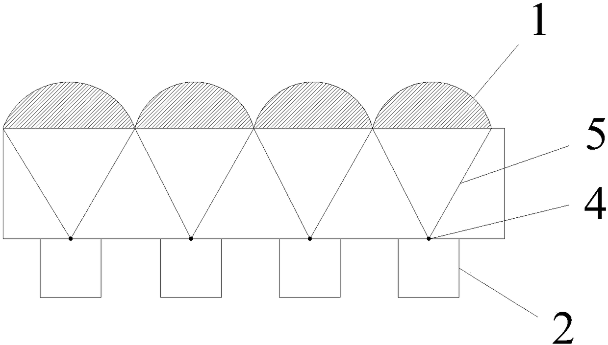
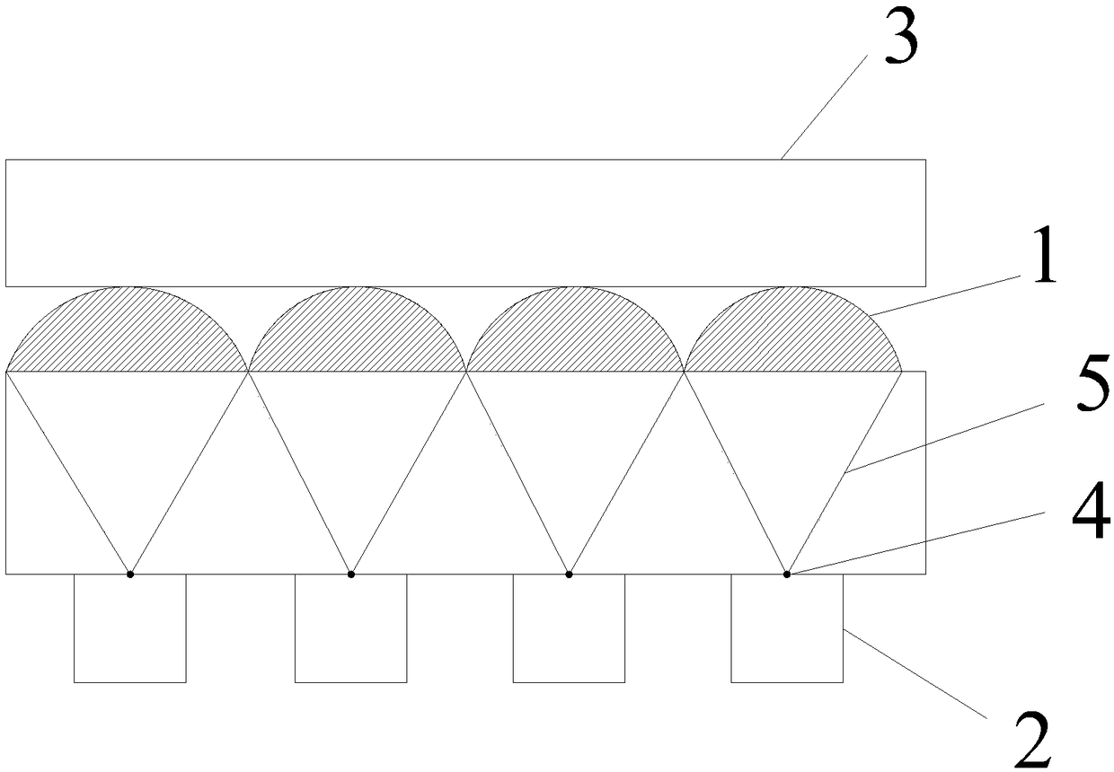
[0027] like figure 1 As shown, an embodiment of the present invention provides a collimated backlight structure, which includes a microlens array 1 and a light source 2 distributed in a matrix. The light source 2 is disposed on one side of the microlens array 1, and the light source 2 is a light-emitting device, such as an LED lamp. The light source 2 is used to emit light from one side of the microlens array 1 and pass through each microlens in the microlens array 1 to illuminate the display screen 3 to form the backlight light of the display screen 3 .

[0028] In order to mak...


PUM


Abstract

The invention discloses a collimating backlight structure, a display device thereof, a double-screen display device, and a multi-screen display device. The collimating backlight structure comprises amicrolens array and a light source, wherein the light source is arranged on one side of the microlens array, and is used for emitting an emitted light from one side of the microlens array and enablingthe light to penetrate through the microlens array; and multiple light through holes are formed between the light source and the microlens array, are arranged corresponding to microlenses of the microlens array one to one, and are located on focuses of the microlenses of the microlens array. According to the collimating backlight structure, the emitted backlight is a collimating light, so that abacklight effect of the collimating backlight structure is improved.

Description

technical field [0001] The invention relates to the field of display, in particular to a collimated backlight structure and a display device thereof, a dual-screen display device and a multi-screen display device. Background technique [0002] The backlight module in the prior art generally includes a base substrate and a surrounding plate arranged on the base substrate. The surrounding plate and the base substrate form a plurality of grooves, each groove is provided with a light source, and each groove is provided with a light source. The notch is provided with a controllable light-transmitting structure, and a microlens is arranged above the controllable light-transmitting structure; the controllable light-transmitting structure includes a light-transmitting area and an adjustable area; in the normal viewing angle mode, the adjustable area and the light-transmitting area are All regions are light-transmitting, and the light source of the backlight module in the prior art g...

Claims


Application Information

Patent Timeline
IPC IPC(8): F21S8/00F21V5/00F21V5/04F21V7/00F21Y115/10
CPCF21S8/00F21V5/004F21V5/04F21V7/00F21Y2115/10
Inventor 朱劲野
Owner BOE TECH GRP CO LTD
Learn More