
Insulated wire stripper

A wire stripper and insulated wire technology, which is applied in the direction of line/collector parts, cable installation devices, electrical components, etc., can solve the inconvenience of operation, the inability to complete the circular cutting of cables, and the inability to accurately judge whether the insulation layer is completely cut through and other problems, to achieve the effect of controllable cutting depth

Inactive Publication Date: 2018-07-10
YANTAI MUPING POWER SUPPLY CO OF STATE GRID SHANDONG ELECTRIC POWER CO
View PDF3 Cites 14 Cited by
  • Summary
  • Abstract
  • Description
  • Claims
  • Application Information

AI Technical Summary

Problems solved by technology

[0004] (1) Corresponding to cables with different wire diameters, different taper sleeves need to be replaced, resulting in inconvenient operation
[0005] (2) Only the axis cutting of the cable can be realized, but the circumferential cutting of the cable cannot be completed
[0006] (3) As for the cutting depth, only the personal experience of the operator can only be relied on, and it is impossible to accurately judge whether the insulating layer is completely cut through

Method used


Image

  • Insulated wire stripper
  • Insulated wire stripper
  • Insulated wire stripper

Examples


Embodiment Construction

[0025] The present invention will be described in further detail below in conjunction with the accompanying drawings.

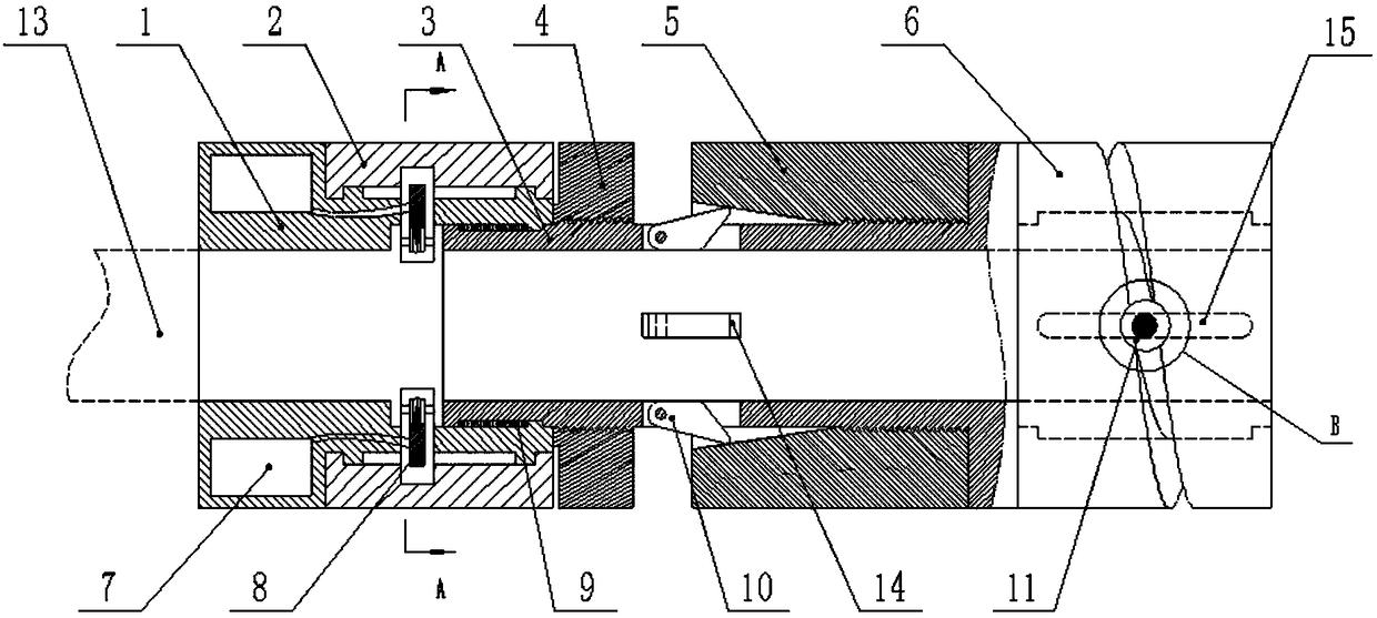
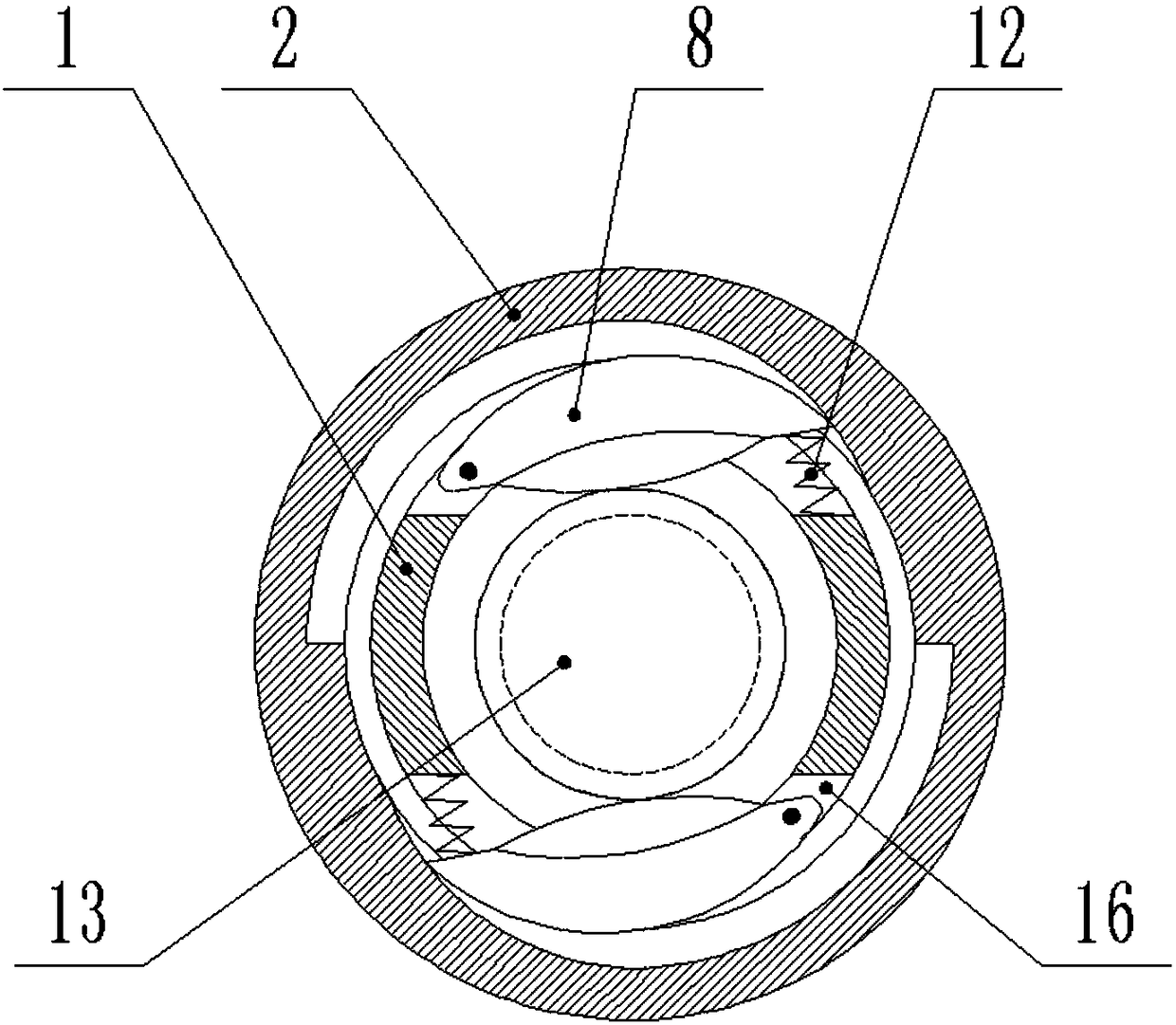
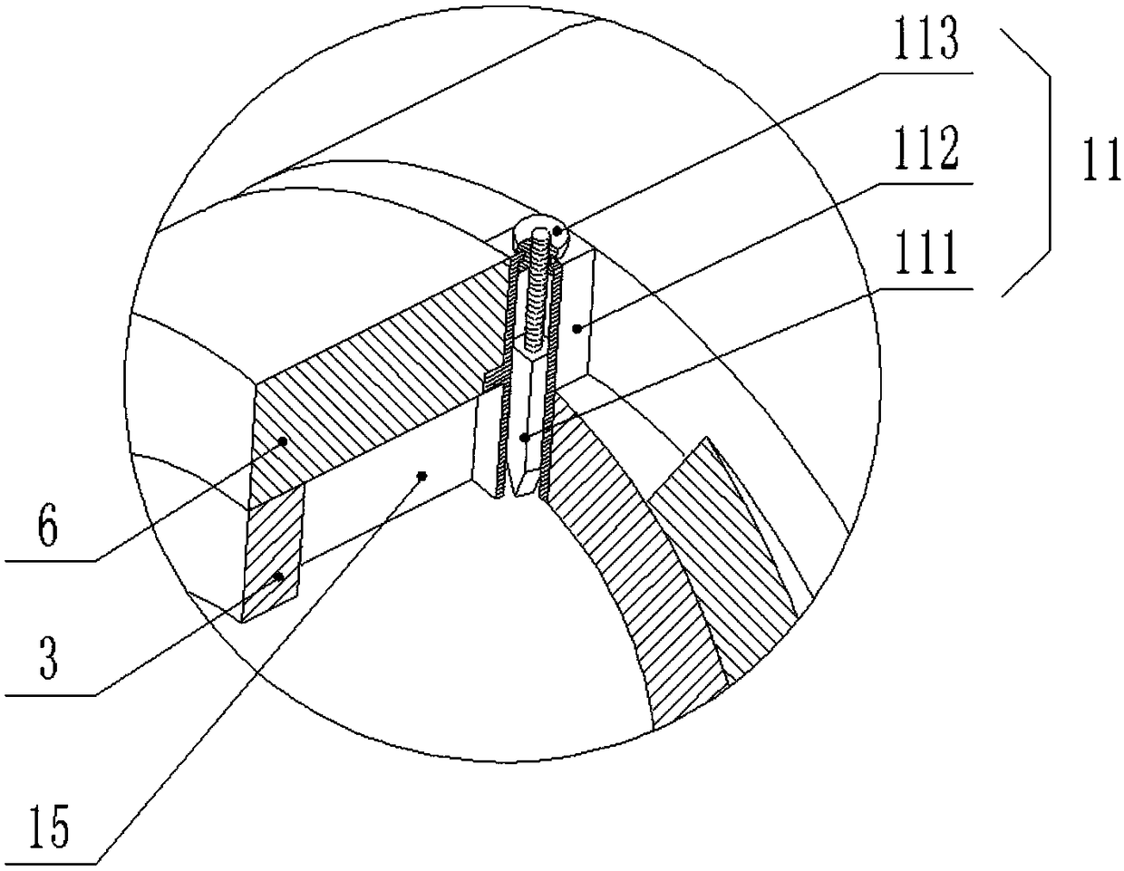
[0026] An insulated wire stripper, including an inner cylinder 3, the outer ring of the inner cylinder 3 is sequentially fitted with a middle sleeve 1, an ejection sleeve 4, a clamping sleeve 5, and a slitting sleeve 6 , the middle sleeve 1 can rotate along the circumference of the inner cylinder 3 and can also slide along its axial direction. An annular cavity is provided at the joint between the middle sleeve 1 and the inner cylinder 3, and a top is set in the annular cavity. The ejection spring 9, the ejection spring 9 is in a compressed state, the two ends of the ejection spring 9 are respectively abutted against the ring boss at the end of the middle sleeve 1 and the inner cylinder 3, and the ejection sleeve 4 is rotated counterclockwise The ejection sleeve 4 will move to the left, so that the middle sleeve 1 will overcome the elastic force of the ejecti...


PUM


Abstract

The invention relates to an insulated wire stripper, comprising an inner cylinder body. The inner cylinder body is sleeved with a middle sleeve, an ejection sleeve, a clamping sleeve and a longitudinal cutting sleeve on the outer ring sequentially from left to right. The middle sleeve is also sleeved with an annular cutting sleeve on the outer ring. Four circumferentially distributed rectangular clamping block mounting grooves are formed in the central cylinder wall of the inner cylinder body. Four clamping blocks are respectively hinged in the four clamping block mounting grooves. The outer end of each clamping block abuts against a conical opening wall of the clamping sleeve. A spiral guiding groove is formed in the wall of the longitudinal cutting sleeve. An axial guiding groove is formed in the cylinder wall of the inner cylinder body. A longitudinal slider is mounted at the intersection position of the two guiding grooves. Two annular cutter mounting grooves are symmetrically arranged at the circumferential center of the central cylinder wall of the middle sleeve. Two annular cutters in central symmetry and in the shape of an arc sheet are respectively mounted in the two annular cutter mounting grooves. The outer side of each annular cutter abuts against the inner wall of an involute groove of the inner ring of the annular cutting sleeve.

Description

technical field [0001] The invention relates to the technical field of electric construction tools, in particular to an insulating wire stripper. Background technique [0002] At present, with the rapid development of the economy, the urban power grid is also developing rapidly, and the demand for power equipment is gradually increasing. During the construction of power equipment, a large number of cables need to be laid, and the cable terminals need to be stripped to connect the terminals. In the prior art, simple tools such as a utility knife, an electrician's knife, and needle-nose pliers are commonly used for cable stripping. Stripping wires requires the operator's personal experience to control the stripping. However, these tools are difficult to operate, labor-intensive, and work inefficient. [0003] Chinese patent CN204992440U discloses "a wire stripper". The wire stripper is guided by a guided wire diameter taper sleeve, and the wire is stripped by means of a fixe...

Claims


Application Information

Patent Timeline
IPC IPC(8): H01R43/28
CPCH01R43/28H02G1/1231H02G1/1268
Inventor 李书锋孔庆晓王振强曲永波姜旭博孙金玉洁吴伟平臧浩洋唐欢刘永鹏白轩宇杨馥华林世宁常宗学
Owner YANTAI MUPING POWER SUPPLY CO OF STATE GRID SHANDONG ELECTRIC POWER CO
Learn More