Composite broach

A technology of spline broach and keyway broach, which is applied in the direction of broach, broaching machine, metal processing equipment, etc. It can solve the problems of broach breakage, heavy workload of workers, and high resistance, so as to prolong the service life and improve the cutting efficiency. efficiency effect

Inactive Publication Date: 2011-11-02
王树彬
View PDF0 Cites 10 Cited by
  • Summary
  • Abstract
  • Description
  • Claims
  • Application Information

AI Technical Summary

Problems solved by technology

[0002] At present, the broaches used in mechanical processing are composed of chamfering edge, auxiliary cutting edge, cutting surface, auxiliary cutting surface, and cutting edge. The cutting edge is roughly in a single cutting force mode, that is, although each broach has multiple cutting , each cutting strip has a complete cutting edge. The cutting edge of this structure, especially the tapered broach, is subjected to a large force and resistance as a whole, which often causes the broach to break, waste products, or even work-related accidents. Knife, due to the large resistance, it is more laborious to pull the hole, the workload of the workers is very large, and the efficiency is very low

Method used


Image

  • Composite broach
  • Composite broach
  • Composite broach

Examples


Embodiment approach 1

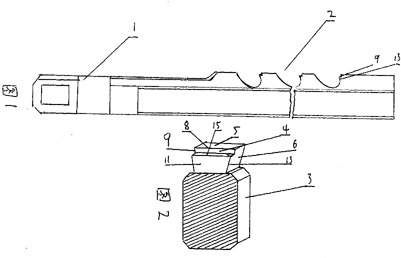
[0022] A composite broach such as figure 1 figure 2 As shown, the composite broach of the first embodiment of the present invention, specifically the composite keyway broach, includes a tool handle 1 and a tool head 2, the tool handle 1 and the tool head 2 are formed into one piece, and the tool head 2 is integrally formed A plurality of cutting bodies 3 are provided, and each cutting body 3 has a cutting face 4, the back side of the cutting face 4 facing the cutting direction is the rear cutting face 5, and the side of the side of the cutting face 4 is the side Cutting surface 6, at least one cutting edge 8 is formed when the cutting surface 4 intersects with the rear cutting surface 5, at least one side cutting edge 9 is formed when the cutting surface 4 intersects with the side cutting surface 6, and at least one side cutting edge 9 is formed on the inner side of the cutting surface 4. The stepped composite cutting surface 11 and at least one stage of the composite side c...

Embodiment approach 2

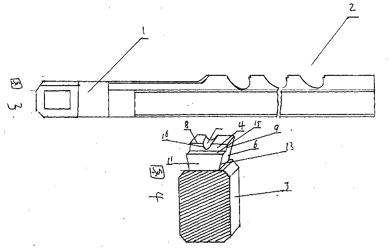
[0025] A composite broach such as image 3 Figure 4 As shown, the composite broach of the second embodiment of the present invention, specifically a composite keyway broach, includes a tool handle 1 and a tool head 2, the tool handle 1 and the tool head 2 are formed into one piece, and the tool head 2 is integrally formed A plurality of cutting bodies 3 are provided, and each cutting body 3 has a cutting face 4, the back side of the cutting face 4 facing the cutting direction is the rear cutting face 5, and the side of the side of the cutting face 4 is the side Cutting surface 6, at least one cutting edge 8 is formed when the cutting surface 4 intersects with the rear cutting surface 5, at least one side cutting edge 9 is formed when the cutting surface 4 intersects with the side cutting surface 6, and at least one side cutting edge 9 is formed on the inner side of the cutting surface 4. The stepped composite cutting surface 11 and at least one stage of the composite side cu...

Embodiment approach 3

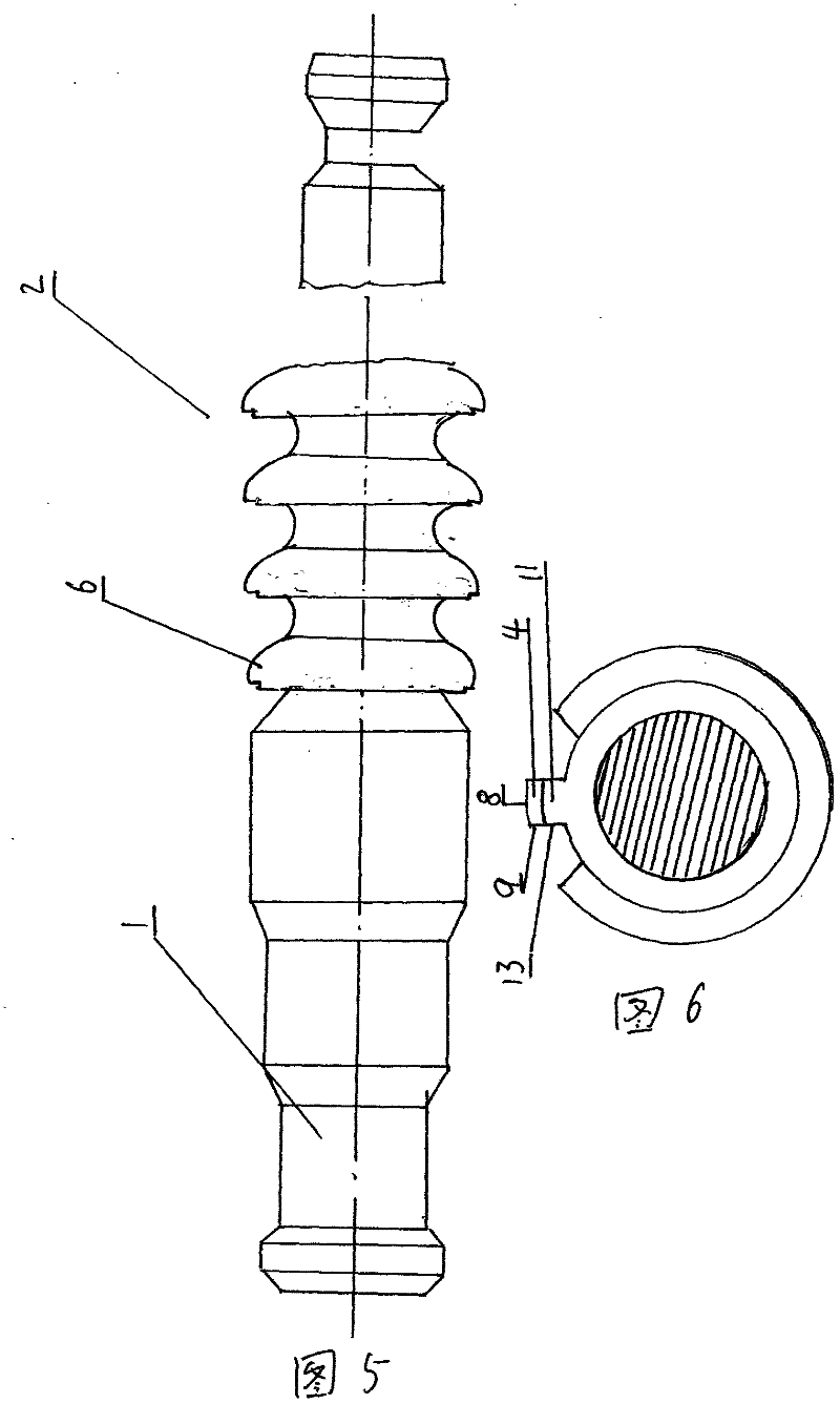
[0028] A composite broach such as Figure 5 Image 6 As shown, the composite broach of the third embodiment of the present invention, specifically a small-diameter centering rectangular spline composite broach, includes a tool handle 1 and a tool head 2, and the tool handle 1 and the tool head 2 are formed as a whole, The tool head 2 is integrally provided with a plurality of cutting tool bodies 3, and each cutting tool body 3 has a cutting surface 4, the back side of the cutting surface 4 facing the cutting direction is a rear cutting surface 5, and the side of the cutting surface 4 The surface of the cutting surface is a side cutting surface 6, the cutting surface 4 intersects with the rear cutting surface 5 to form at least one cutting edge 8, and the cutting surface 4 intersects the side cutting surface 6 to form at least one side cutting edge 9. The inner side of the cutting surface 4 is convex At least one level of stepped compound cutting surface 11 and at least one le...


PUM


Abstract

The invention provides a composite broach, which has the advantages of high heat radiating efficiency, small resistance, long service life, and high cracking-resistant strength of a cutting blade and is easy for positioning during broaching. The composite broach comprises a broach head and is characterized in that a plurality of annular cutter blocks are configured on the broach head, and a cutting face or a chamfering face is formed on the broach head; a composite cutting face is convexly arranged at the inner side of the cutting face and provided with a composite cutting blade or a composite lateral cutting blade and a reinforcing platform; and a notched blade is arranged on the cutting blade or the lateral cutting blade, a groove extends to the cutting face or a rear cutting face or a lateral cutting face in an opening manner or is distributed on the cutting face or the rear cutting face or the lateral cutting face or the composite cutting face or a composite lateral cutting face side or a composite rear cutting face in a gradually enlarged shape.

Description

Technical field: [0001] The invention relates to a broach which is used in the broaching of drilling and other processes in machining. Background technique: [0002] The broaches currently used in machining are composed of a chamfering edge, a secondary cutting edge, a cutting surface, a secondary cutting surface and a cutting edge. , There is a complete cutting edge on each cutting strip. The cutting edge of this structure, especially the tapered broach, has a large overall force and resistance, which often causes the broach to break, cause waste, and even cause work accidents. Knives, due to the large resistance, are more laborious when pulling holes, and the workers have a lot of work and low efficiency. Invention content: [0003] The present invention is proposed in view of the above-mentioned problems, and one purpose is to provide a new type of composite broach, which has high heat dissipation efficiency, low cutting resistance and long service life. [0004] In o...

Claims


Application Information

Patent Timeline
Patent Type & Authority Applications(China)
IPC IPC(8): B23D43/00
Inventor 李仕清王树彬
Owner 王树彬
Why Eureka
Try Eureka