Wireless charge unicoil emitting and receiving positioning charge system

A wireless charging and charging system technology, applied to electrical components, circuit devices, etc., to achieve the effects of avoiding power waste, easy to carry, and convenient and fast wireless charging

Active Publication Date: 2018-07-10
深圳市遨捷智能科技有限公司
View PDF8 Cites 2 Cited by
  • Summary
  • Abstract
  • Description
  • Claims
  • Application Information

AI Technical Summary

Problems solved by technology

[0005] In view of the above problems, the technical problem to be solved by the present invention is to provide a wireless charging single-coil transmitting and receiving positioning charging system to solve the local wireless charging and receiving status of the wireless charging device that does not support the "transmitting status LED indication function", Problems with manually adjusting to optimal receive coupling

Method used


Image

  • Wireless charge unicoil emitting and receiving positioning charge system
  • Wireless charge unicoil emitting and receiving positioning charge system
  • Wireless charge unicoil emitting and receiving positioning charge system

Examples


specific Embodiment approach 1

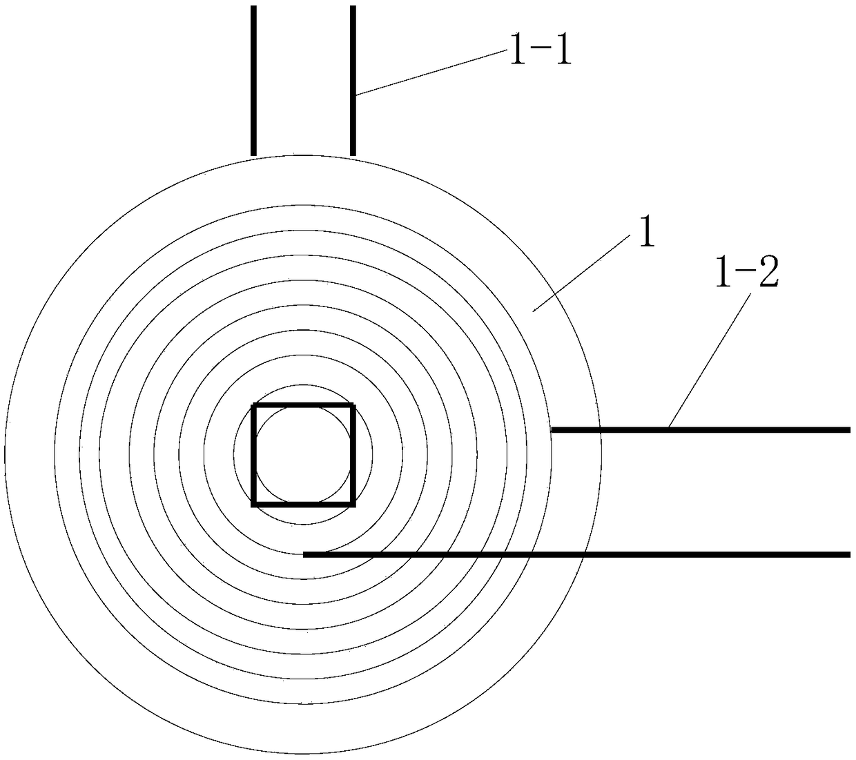
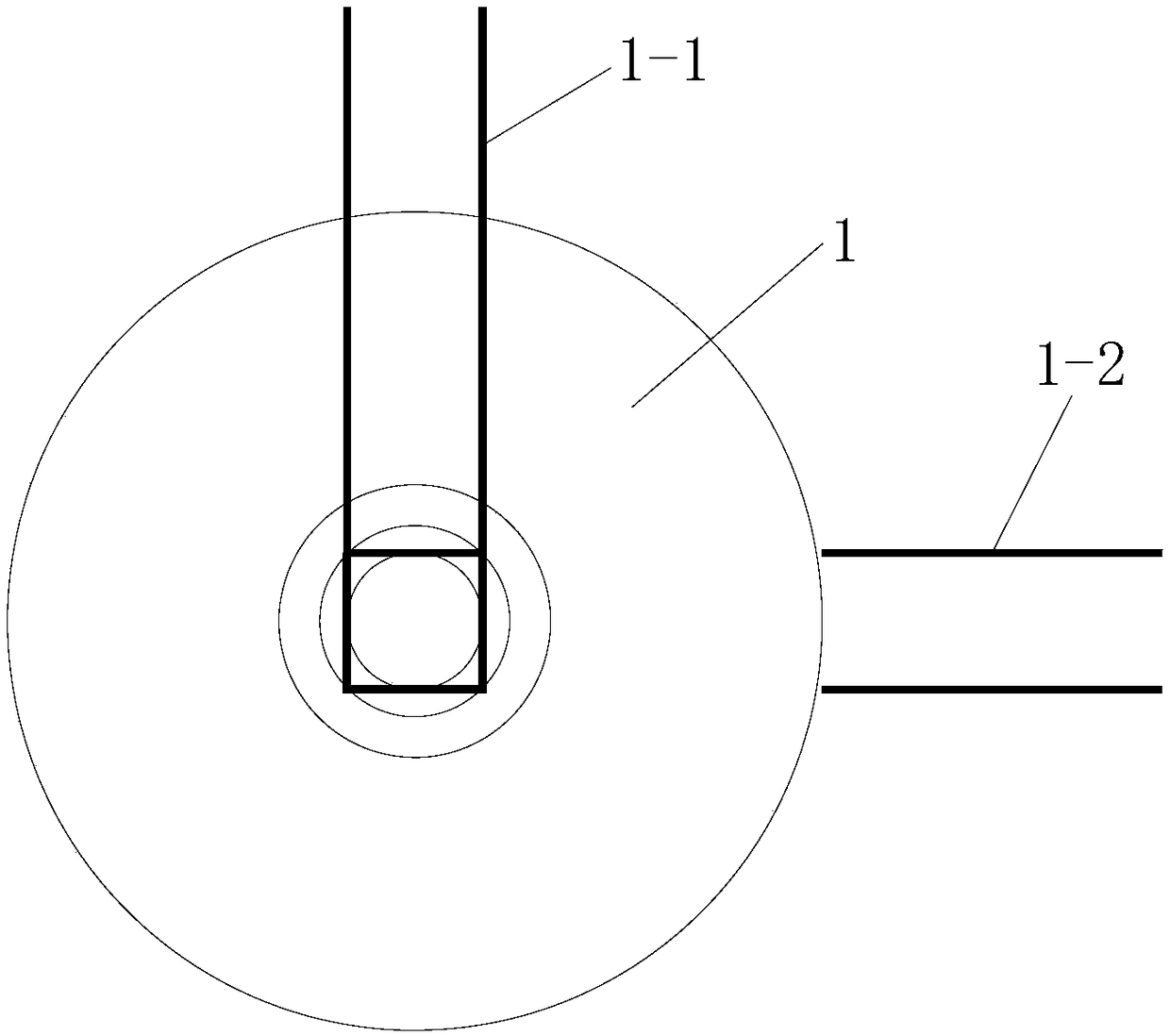
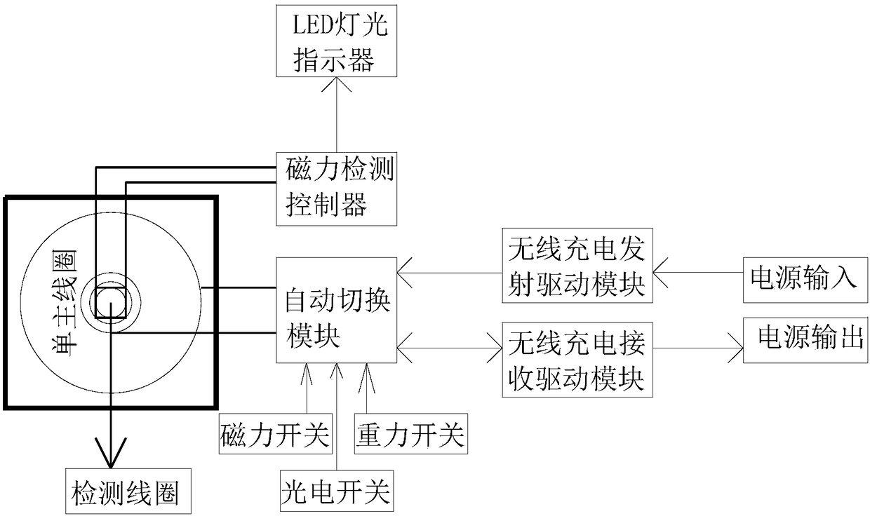
[0021] Specific implementation mode one: as figure 1 , figure 2 , image 3 As shown, this specific embodiment adopts the following technical solutions: This technology adopts a manual version; it includes a main coil 1, a magnetic detection controller, an LED light indicator, an automatic switching module, a magnetic switch, a gravity switch, a photoelectric switch, and a wireless charging Transmitting drive module, wireless charging receiving drive module; the external power supply is connected to the power input terminal, the power input terminal inputs power to the wireless charging transmitting drive module, the wireless charging transmitting drive module is electrically connected to the automatic switching module, and the automatic switching module is connected to the main coil 1 The terminals 1-2 are connected, and the magnetic switch, gravity switch, and photoelectric switch are all connected to the input end of the automatic switching module. The automatic switching ...

specific Embodiment approach 2

[0034] Specific implementation mode two: the difference between this specific implementation mode and specific implementation mode one is: as Figure 4 As shown, this specific embodiment is a manual plus automatic version, which is based on the single manual version, adding an automatic positioning function; it also includes a mobile base, a mechanical drive controller, a matrix positioning controller, and a wireless charging desktop; The main coil is set, and the mobile base is connected with a helical shaft that moves along the X-axis and Y-axis directions. The helical shaft is connected to the shaft of the motor through a sleeve, and the motor is connected to the mechanical drive controller through a wire. The mechanical The drive controller controls the motor to work, the wireless charging desktop is connected to the matrix positioning controller through wires, the matrix positioning controller is connected to the mechanical drive controller, and the magnetic force detectio...


PUM


Abstract

The present invention discloses a wireless charge unicoil emitting and receiving positioning charge system, and relates to the technical field of wireless charge. An automatic switching module switches a work state of a main coil to an emitting or receiving state, a magnetic switch, a gravity switch and an optoelectronic switch which are coordinated in switching are arranged around the main coil,a power supply input end inputs a power supply to a wireless charge emitting drive module, the wireless charge emitting drive module is electrically connected with the automatic switching module, theautomatic switching module is connected with a wiring terminal of the main coil, and the magnetic switch, the gravity switch and the optoelectronic switch are connected with the input end of the automatic switching module. The serious problems of heating of a wireless charge emitting state with poor coupling and heating of a wireless receiving state are effectively solved; the wireless charge efficiency is higher, electric power waste is avoided, the temperature is reduced, and safety performance is improved, and wireless charge is more convenient and rapid; products are lighter and thinner and easy to carry, the cost is effectively reduced, the structure is more stable and reliable, and unnecessary resource waste is avoided.

Description

technical field [0001] The invention belongs to the technical field of wireless charging, and in particular relates to a wireless charging single-coil transmitting and receiving positioning charging system. Background technique [0002] In the existing wireless charging technology, independent coils and circuits are used for transmitting and receiving. If portable wireless transmitting and receiving charging products are realized, the thickness of the product will be significantly increased, the difficulty of the manufacturing process will be increased, and the cost of the product will be increased. [0003] The existing wireless charging products place the mobile phone at any position. Only alignment can achieve good coupling to achieve the highest wireless charging efficiency. Random placement is actually not a good coupling; manual placement is mainly because there is no reference for people to adjust. [0004] Existing desktop and portable wireless charging products cann...

Claims


Application Information

Patent Timeline
Patent Type & Authority Applications(China)
IPC IPC(8): H02J50/10H02J50/80
CPCH02J50/10H02J50/80
Inventor 李海波
Owner 深圳市遨捷智能科技有限公司
Why Eureka
Try Eureka