Current-sharing bypass circuit of power unit of high-voltage inverter

A high-voltage frequency converter and power unit technology, applied in the direction of output power conversion devices, electrical components, etc., can solve the problems of limited conduction capacity of a single thyristor, high cost, and the conduction capacity of a single thyristor is lower than the actual demand.

Inactive Publication Date: 2014-10-01
BEIJING LEADER & HARVEST ELECTRIC TECH
View PDF7 Cites 0 Cited by
  • Summary
  • Abstract
  • Description
  • Claims
  • Application Information

AI Technical Summary

Problems solved by technology

[0004] Under this circuit topology, since only one thyristor participates in bypass operation, limited by the current manufacturing level of power semiconductor devices, the conduction capacity of a single thyristor is limited. When the current conduction capacity of a single thyristor is lower than the actual demand
In order to meet the bypass requirements of the power unit of the high-voltage frequency converter with large power, one method is to use thyristors with larger capacity and stronger conductivity. progress; another approach is to modify existing circuit topologies to meet the above requirements

Method used


Image

  • Current-sharing bypass circuit of power unit of high-voltage inverter
  • Current-sharing bypass circuit of power unit of high-voltage inverter
  • Current-sharing bypass circuit of power unit of high-voltage inverter

Examples


Embodiment Construction

[0021] The present invention will be described in further detail below in conjunction with the accompanying drawings and embodiments.

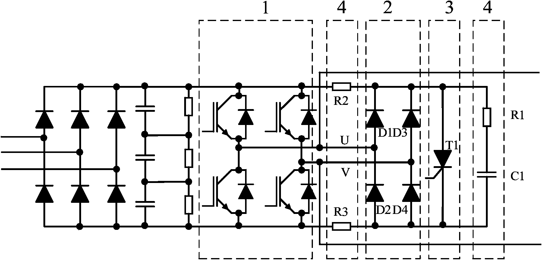
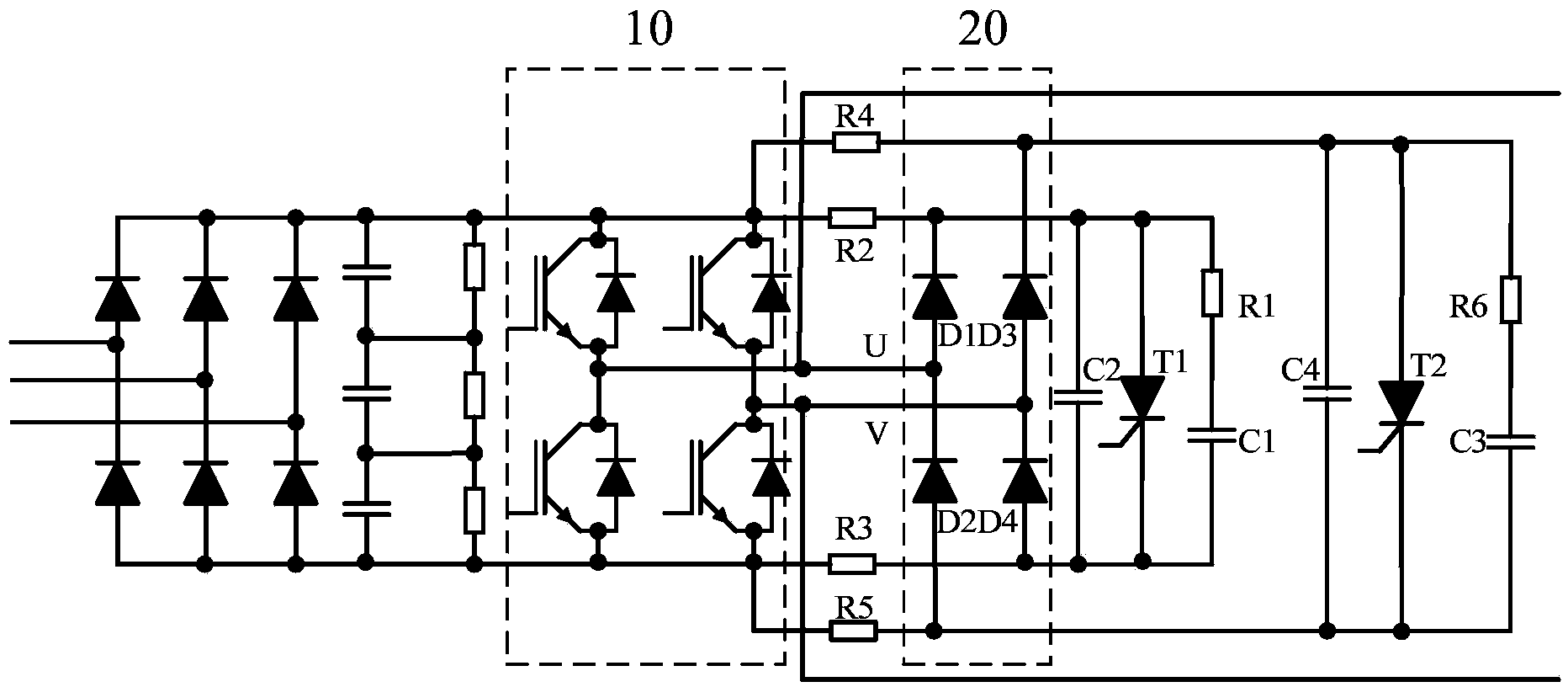
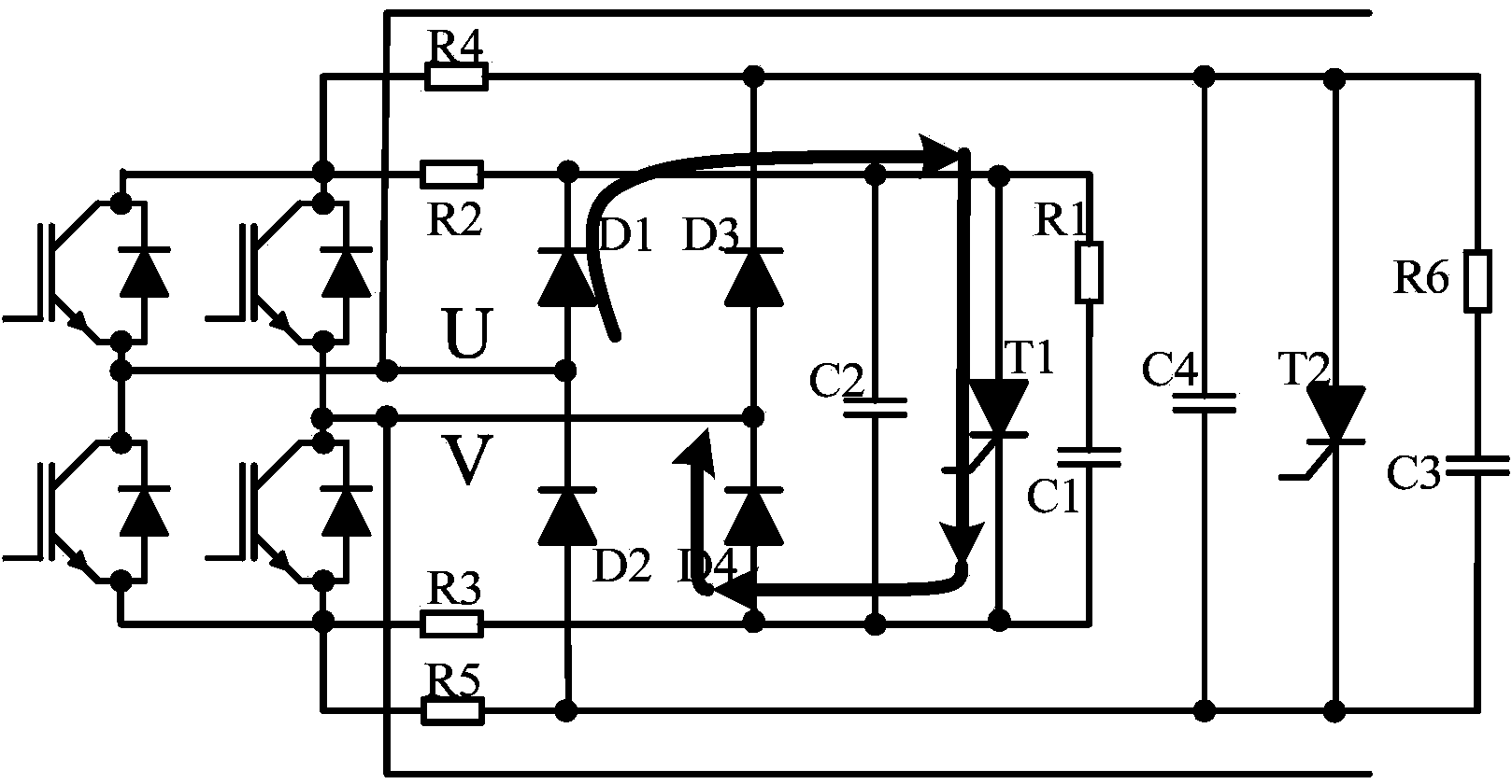
[0022] figure 2 It is the circuit principle diagram of the bypass circuit of the power unit of the current equalizing high-voltage frequency converter disclosed by the present invention. As shown in the figure, the bypass circuit of the power unit of the current equalizing high-voltage frequency converter disclosed by the present invention includes a single-phase full-wave diode rectifier bridge 20 arranged beside the H inverter bridge 10, a first thyristor, and a first pre-charging resistor and a first buffer circuit connected in parallel with the first thyristor T1, further comprising: a second thyristor T2, a second pre-charging resistor, and a second buffer circuit connected in parallel with the second thyristor T2;

[0023] The single-phase full-wave diode rectifier bridge 20 includes four diodes D1-D4, and the cathodes of the two diode...


PUM


Abstract

The invention provides a current-sharing bypass circuit of a power unit of a high-voltage inverter. The current-sharing bypass circuit comprises a single-phase full-wave diode-bridge rectifier arranged beside an H-bridge inverter, a first thyristor, a second precharging resistor, a first buffer circuit, a second thyristor, a second precharging resistor and a second buffer circuit. The cathodes of two diodes, connected with the direct-current positive output end of a bridge rectifier, in the single-phase full-wave diode-bridge rectifier are connected with the anode of the first thyristor and the anode of the second thyristor respectively, and the anodes of two diodes, connected with the direct-current negative output end of the bridge rectifier, in the single-phase full-wave diode-bridge rectifier are connected with the cathode of the first thyristor and the cathode of the second thyristor respectively. The current-sharing bypass circuit can effectively solve the problem of serious heating of a single thyristor.

Description

technical field [0001] The invention relates to a bypass circuit, in particular to a bypass circuit of a current-equalizing high-voltage frequency converter power unit. Background technique [0002] With the development of power electronics technology, the application of high-voltage frequency converters is becoming more and more extensive. The high-voltage frequency conversion device composed of power units in series is favored by the majority of users for its excellent performance such as small harmonics and convenient maintenance; the power units are connected in series. During the operation of the high-voltage frequency conversion device, the whole device may fail to operate normally due to the failure of individual power units. In order to improve the stability and reliability of the device, it is necessary to temporarily bypass the faulty power unit to ensure that the device can Continue to run normally. [0003] A form of bypass circuit that is commonly used now is a...

Claims


Application Information

Patent Timeline
Patent Type & Authority Applications(China)
IPC IPC(8): H02M1/32
Inventor 杨继伟
Owner BEIJING LEADER & HARVEST ELECTRIC TECH
Why Eureka
Try Eureka