Supercharge Your Innovation With Domain-Expert AI Agents!

Dust collector and dust retaining device applied to same

A vacuum cleaner and dust blocking technology, which is applied to vacuum cleaner storage devices, vacuum cleaners, applications, etc., can solve the problems of easy dust clogging, unsmooth rotation of dust baffles, holes and shafts that are difficult to disassemble and clean, etc., to achieve the effect of improving the use effect.

Pending Publication Date: 2018-07-13
SUZHOU CHUNJU ELECTRIC CO LTD
View PDF0 Cites 0 Cited by
  • Summary
  • Abstract
  • Description
  • Claims
  • Application Information

AI Technical Summary

Problems solved by technology

However, in use, we also found that after long-term use of the dust cup or dust bag in the vacuum cleaner, some fine dust is easy to block the holes for assembly on the dust shield and the position of the shaft, which will lead to dust blocking The plate does not rotate smoothly or even does not rotate, and it is difficult to disassemble and clean the holes and shafts
At the same time, after the function of the dust shield is affected, when the machine stops working, the debris or larger dust in the dust cup or dust bag will fall out, requiring the user to perform a second cleaning, which will affect the user's use effect

Method used


Image

  • Dust collector and dust retaining device applied to same
  • Dust collector and dust retaining device applied to same
  • Dust collector and dust retaining device applied to same

Examples


Embodiment 1

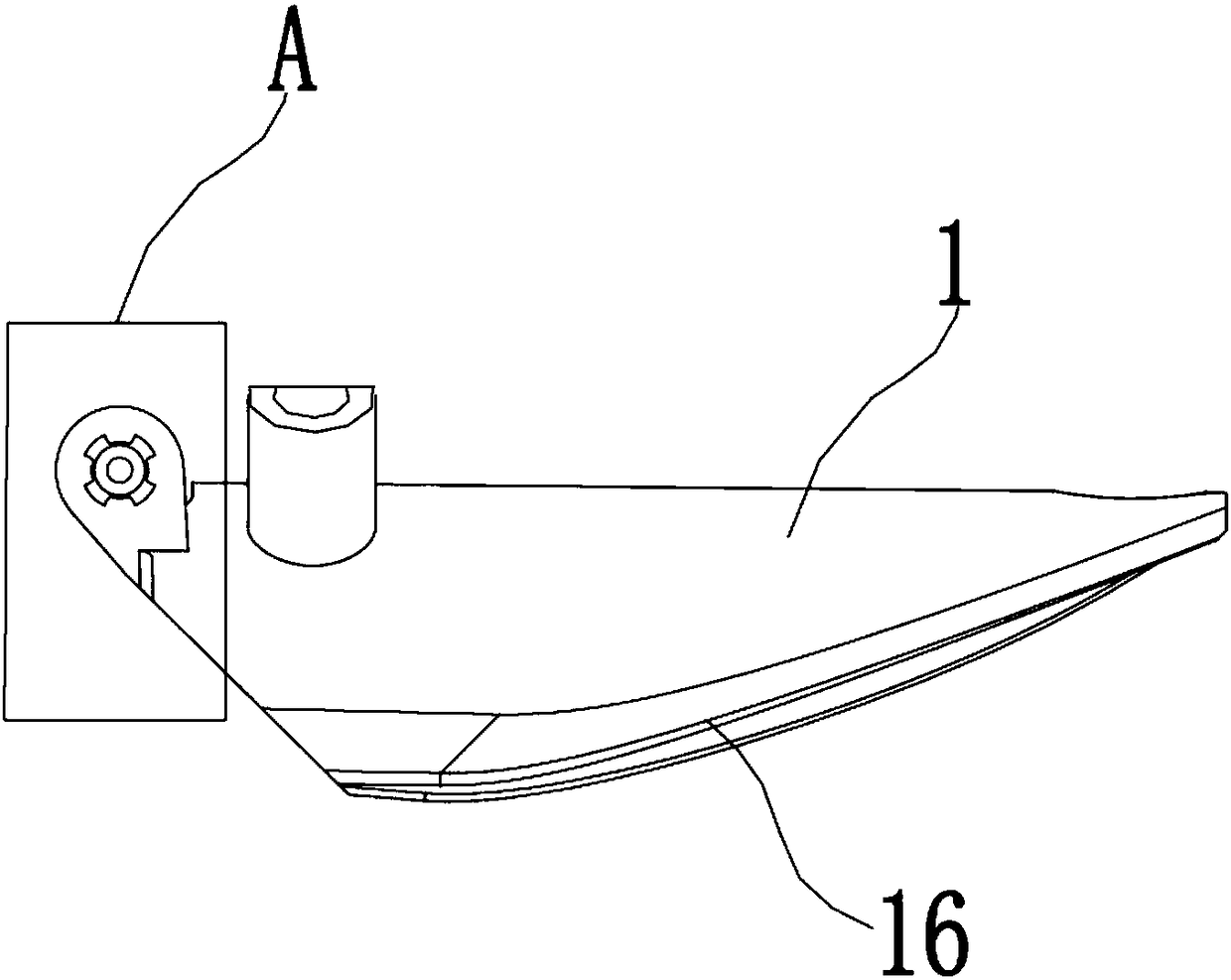
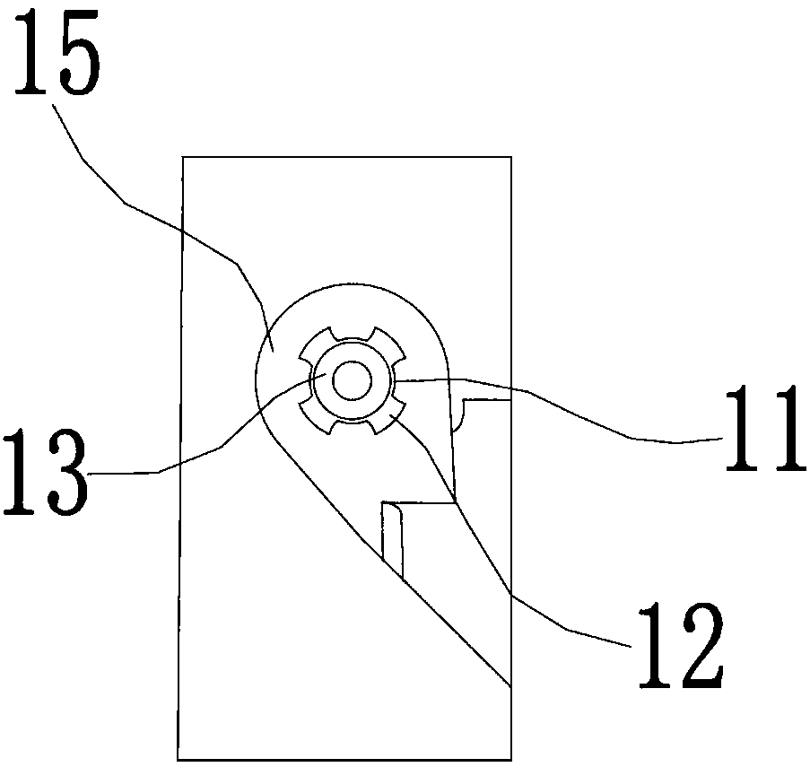
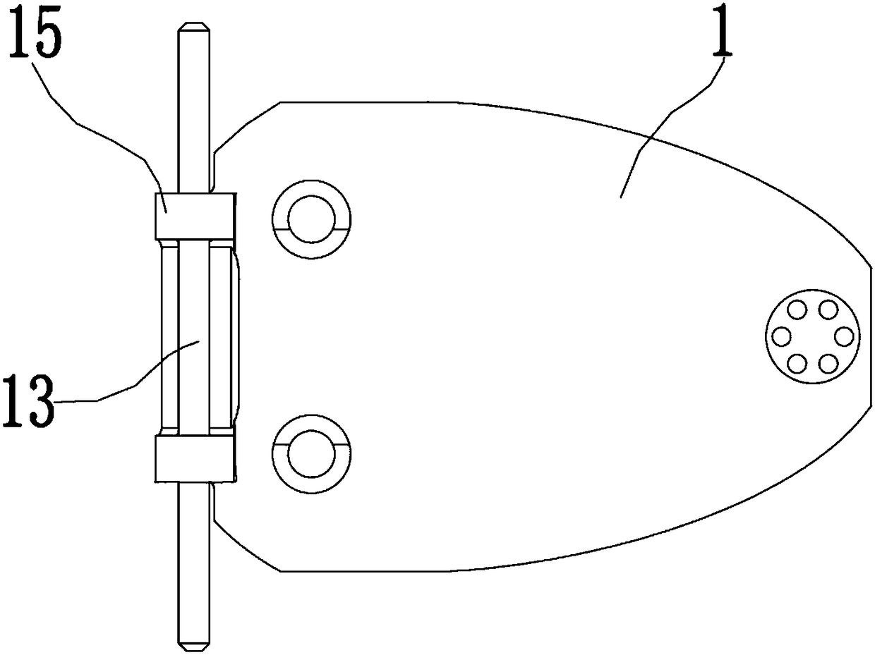
[0026] see Figure 1 to Figure 7 , the figure shows a dust-blocking device applied to a vacuum cleaner provided by an embodiment of the present invention, which includes a dust-blocking part 1, which is a plate with a tapered surface 16 at the bottom, and the dust-blocking part 1 is rotatable Installed at the air inlet 21 of the dust storage part 2, the dust blocking part 1 has a convex strip 15, the assembly hole 11 runs through the convex strip 15 along the axial direction of the convex strip 15, the assembly hole 11 is a round hole, and the assembly hole 11 The inner wall is provided with a plurality of grooves 12, four of which are specifically provided in this embodiment. The plurality of grooves 12 form a spline groove structure. The hole body 22 and the rotating shaft 13 pass through the two hole bodies 22 and the assembly hole 11 at the same time. Wherein, the dust storage component 2 is specifically a dust cup, and may also be a dust bag or the like.

[0027] At the...

Embodiment 2

[0030] Others are the same as those described in the first embodiment, except that only one tank body 12 is selectively provided.

Embodiment 3

[0032] continue to see Figure 1 to Figure 4 , the figure shows a dust blocking device applied to vacuum cleaners provided by Embodiment 3 of the present invention. On the basis of the above embodiments, this embodiment further makes the following technical solutions as improvements: the assembly hole 11 includes The two hole units 14 are coaxially arranged, and there is an axial gap 141 between the two hole units 14 . Through the setting of the above structure, firstly, the assembly length of the assembly hole and the rotating shaft on the dust-blocking part can be shortened, the contact area between the assembly hole and the rotating shaft is reduced, and the dust is prevented from being blocked here; The setting of the gap enables the dust that is centrifugally fly out to be discharged from the opposite sides of the assembly hole, and the dust discharge efficiency is higher.


PUM


Abstract

The invention provides a dust retaining device applied to a dust collector. The dust retaining device comprises a dust retaining component. The dust retaining component can be mounted at an air inletof a dust storage component rotationally. An assembly hole is formed in the dust retaining component. At least one slot is formed in the inner wall of the assembly hole. A rotating shaft is arranged in the assembly hole penetratingly. The invention further provides the dust collector. Compared with the prior art, the dust retaining device has the advantages that dust blocking at hole and shaft positions of the dust retaining component can be effectively prevented, and application effect is improved.

Description

technical field [0001] The invention relates to the field of vacuum cleaners, in particular to a dust blocking device and a vacuum cleaner applied to a vacuum cleaner. Background technique [0002] In the component composition of the vacuum cleaner, the dust cup or the dust bag is mainly used as the dust storage part of the vacuum cleaner, which temporarily stores the dust inhaled by the vacuum cleaner daily, which is convenient for the user to clean up in a centralized manner. [0003] In some vacuum cleaners currently on the market, in order to realize the dust blocking effect on the dust cup or the dust bag, a dust shield is installed at the air inlet of the dust cup or the dust bag. However, in use, we also found that after long-term use of the dust cup or dust bag in the vacuum cleaner, some fine dust is easy to block the holes for assembly on the dust shield and the position of the shaft, which will lead to dust blocking The plate does not rotate smoothly, or even doe...

Claims


Application Information

Patent Timeline
IPC IPC(8): A47L9/00A47L9/02
CPCA47L9/0009A47L9/02
Inventor 费飞
Owner SUZHOU CHUNJU ELECTRIC CO LTD
Features
  • R&D
  • Intellectual Property
  • Life Sciences
  • Materials
  • Tech Scout
  • Unparalleled Data Quality
  • Higher Quality Content
  • 60% Fewer Hallucinations
Learn More