An automatic film tearing machine for film removal of light guide plate

A light guide plate, automatic technology, applied in the direction of lamination, chemical instruments and methods, lamination auxiliary operation, etc., can solve the problems of uncontrollable product surface quality, staff's hand acid, pollution of defective light guide plate, etc.

Active Publication Date: 2020-08-11
SUZHOU QINGJIANG PRECISION MACHINE TECH
View PDF3 Cites 0 Cited by
  • Summary
  • Abstract
  • Description
  • Claims
  • Application Information

AI Technical Summary

Problems solved by technology

There are two problems with this method of film removal. One is that the staff often suffer from hand fatigue and fatigue, and the manual workload is relatively large. Good product, the surface quality of the product cannot be controlled

Method used


Image

  • An automatic film tearing machine for film removal of light guide plate
  • An automatic film tearing machine for film removal of light guide plate
  • An automatic film tearing machine for film removal of light guide plate

Examples


Embodiment Construction

[0017] The following will clearly and completely describe the technical solutions in the embodiments of the present invention with reference to the accompanying drawings in the embodiments of the present invention. Obviously, the described embodiments are only some, not all, embodiments of the present invention. Based on the embodiments of the present invention, all other embodiments obtained by persons of ordinary skill in the art without creative efforts fall within the protection scope of the present invention.

[0018] The specific implementation manner of the present invention will be further described in detail below in conjunction with the schematic diagrams.

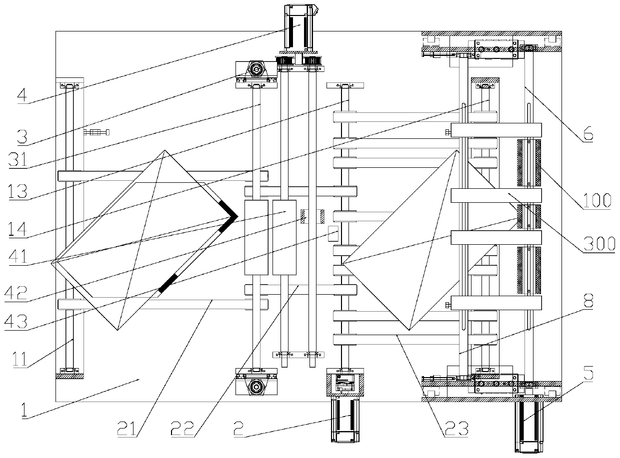
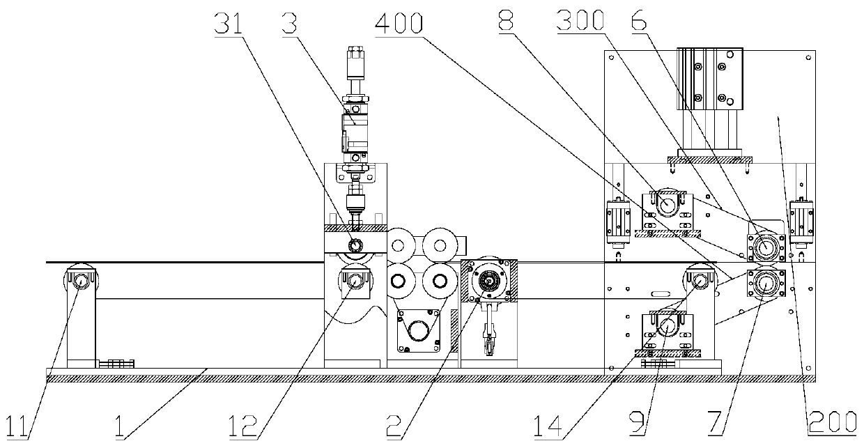
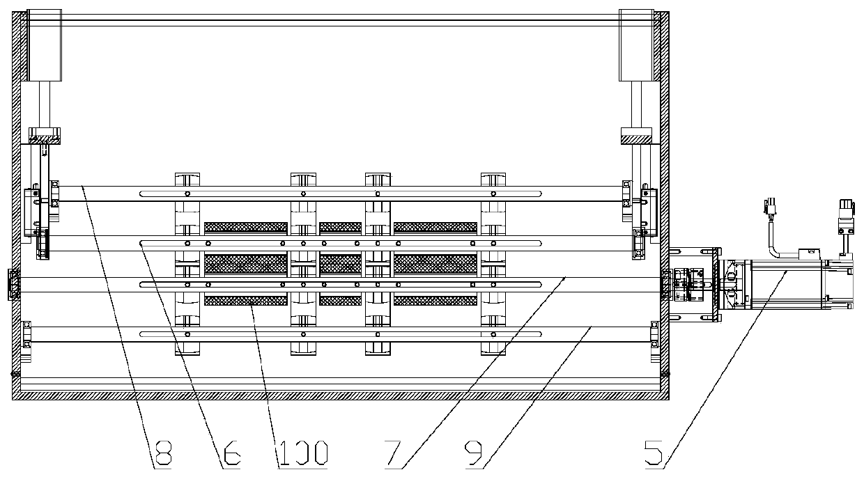
[0019] Such as figure 1 , figure 2 and image 3 As shown, an automatic film tearing machine for removing the film of the light guide plate includes a frame 1, and the frame 1 is sequentially rotated from one side to the other side to be provided with a first feeding roller 11, a second feeding roller 12, The ...


PUM


Abstract

The invention specifically discloses an automatic film tearing machine for removing a film from a light guide plate. The automatic film tearing machine comprises a rack, wherein a conveying roller group is arranged on the rack in a rotatable manner; a conveying belt is arranged on the conveying roller group; a first servo motor axially connected with the conveying roller group is arranged at the side part of the rack; pressing-down cylinders are respectively arranged at positions, which are located at two ends of the conveying roller group, on the rack; a pressing-down roller corresponding tothe conveying roller group is arranged on movable rods of the two pressing-down cylinders in a jointly rotatable manner; a second servo motor is arranged at the side part of the other side of the rack; a correction roller corresponding to the pressing-down roller and a brush wheel are arranged on the rack in a rotatable manner; the correction roller and the brush wheel are both axially connected with the second servo motor; a group of air nozzles corresponding to the brush wheel are also arranged on the rack; the air nozzles are communicated with an external high-pressure air supply device; athird servo motor is arranged at the side part of the rack; and an upper sticky roller group and a lower sticky roller group which are axially connected with the third servo motor are arranged on therack in a rotatable manner. The automatic film tearing machine reduces the workload of a worker and fulfills the aim of automatically tearing off a film.

Description

technical field [0001] The invention relates to auxiliary equipment for the production of light guide plates, in particular to an automatic film tearing machine for film removal of light guide plates. Background technique [0002] The current method of removing the film of the light guide plate is to tear off the protective film on each light guide plate to be produced by the staff with fingers. There are two problems with this method of film removal. One is that the staff often suffer from hand fatigue and fatigue, and the manual workload is relatively large. Good product, the surface quality of the product cannot be controlled. Contents of the invention [0003] In order to solve the above technical problems, we proposed an automatic film tearing machine for removing the film of the light guide plate. Scrap loss. [0004] To achieve the above object, the technical scheme of the present invention is as follows: [0005] An automatic film tearing machine for removing f...

Claims


Application Information

Patent Timeline
Patent Type & Authority Patents(China)
IPC IPC(8): B32B38/10
CPCB32B38/105
Inventor 杨为新
Owner SUZHOU QINGJIANG PRECISION MACHINE TECH
Why Eureka
Try Eureka