
Brake switch structure

A technology of brake switch and switch head, which is applied to electric switches, brakes, brake components, etc., and can solve problems such as water ingress corrosion

Inactive Publication Date: 2018-07-13
ANHUI JIANGHUAI AUTOMOBILE GRP CORP LTD
View PDF7 Cites 0 Cited by
  • Summary
  • Abstract
  • Description
  • Claims
  • Application Information

AI Technical Summary

Problems solved by technology

[0004] But using this method, the part of the air pipe 1' is still connected to the outside. In the rainy season, the water vapor formed on the chassis during the movement of the car will attach to the exhaust pipe 1' to form water droplets; for example, the position where the water droplets attach is in the exhaust hole Nearby, the air brake switch will suck water droplets into the switch during the intake and exhaust process, resulting in water corrosion

Method used


Image

  • Brake switch structure
  • Brake switch structure

Examples


Embodiment 1

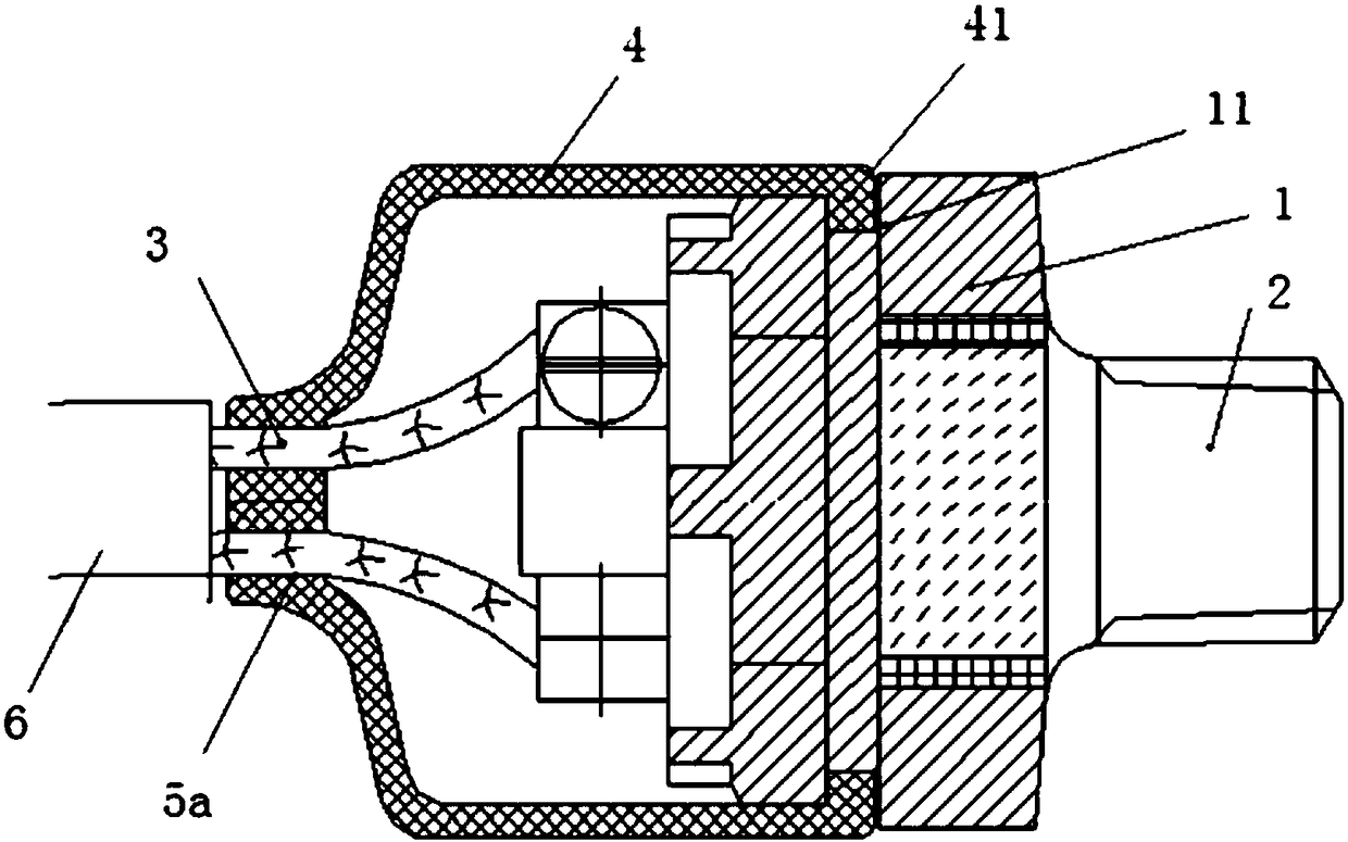
[0023] A brake switch structure, see figure 1 , including: a base 1, a switch head 2, a wire harness 3 and a protective cover 4, one end of the base 1 is a function end, and the other end is a connection end; The protective cover 4 is sleeved on the base 1 to cover the connection end and expose the functional end, so that the switch head 2 is also exposed from the protective cover 4 .

[0024] A through hole 5 a is formed on the protective cover 4 , the wire harness 3 protrudes from the through hole 5 a, and the diameter of the through hole 5 a is smaller than or equal to the outer diameter of the wire harness 3 . Preferably, the protective cover 4 is a rubber member, and the through hole 5a has a certain degree of elasticity, so that it can tighten the wire harness 3, thereby achieving a seal between the through hole 5a and the wire harness 3 to avoid water leakage.

[0025] On the portion between the functional end and the connecting end of the base 1, a circle of connectin...

Embodiment 2

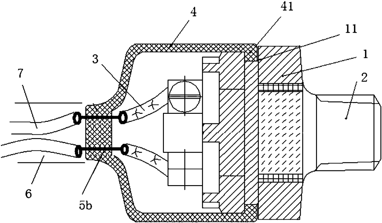
[0029] A brake switch structure, see figure 2 , including: a base 1, a switch head 2, a wire harness 3 and a protective cover 4, one end of the base 1 is a function end, and the other end is a connection end; The protective cover 4 is sleeved on the base 1 to cover the connection end and expose the functional end, so that the switch head 2 is also exposed from the protective cover 4 .

[0030] A connecting terminal 5 b is formed on the protective cover 4 , one end of the connecting terminal 5 b is located inside the protective cover 4 and connected to the wire harness 3 , and the other end of the connecting terminal 5 b protrudes from the protective cover 4 and is connected to the external wire 7 . Preferably, the protective cover 4 is a rubber part. The connection terminal 5b is a conductive structure, and it can be vulcanized with the protective cover 4, or other methods can be used, as long as the connection terminal 5b is guaranteed to be connected inside and outside the...


PUM


Abstract

The invention discloses a brake switch structure, comprising a base, a switch head, a wire harness and a protective hood, wherein one end of the base is a functional end and the other end is a connecting end, the switch head is arranged at the functional end, the wire harness is connected to the connecting end, the protective hood, which sleeves the base, covers the connecting end while exposing the functional end, is provided with via holes, the wire harness extends out of the via holes, and the diameter of the via holes is smaller than the outside diameter of the wire harness. According to the brake switch structure, the connecting end of the base can be prevented from water effectively through the protective hood structure.

Description

technical field [0001] The invention relates to auto parts, in particular to a brake switch structure. Background technique [0002] In some large medium and heavy truck models, in order to accurately and effectively reflect the braking state of the car, the braking signal is often collected directly from the brake valve, and the braking state of the car is judged by detecting the air pressure state of the brake pipeline. Since the brake valve is located on the chassis, the environment in which the brake switch is installed is relatively harsh and requires high water resistance. The traditional air brake switch is a mechanical contact type, one end of which is connected to the brake valve, and the other end needs to be equipped with a vent hole to balance the internal air pressure of the switch so that the contacts can effectively contact, so that at the position of the vent hole A waterproof structure needs to be designed. [0003] In the prior art, see figure 1 , Connec...

Claims


Application Information

Patent Timeline
Patent Type & Authority Applications(China)
IPC IPC(8): H01H9/04B60T17/00
CPCH01H9/04B60T17/00
Inventor 江常兵王佳蔡明明
Owner ANHUI JIANGHUAI AUTOMOBILE GRP CORP LTD
Learn More