
Electronic product protection structure

A technology for protecting structures and electronic products. It is applied in the direction of measuring electrical variables, measuring devices, and instruments. It can solve problems such as laborious, inconvenient, and troublesome, and achieve the effect of protecting the privacy of electricity consumption and facilitating the reading of electricity meters.

Active Publication Date: 2018-07-17
山东贝斯特信息科技有限公司
View PDF14 Cites 0 Cited by
  • Summary
  • Abstract
  • Description
  • Claims
  • Application Information

AI Technical Summary

Problems solved by technology

[0005] The existing technology has the following technical problems: 1. Although the meter can be protected, the meter reading personnel need to use a key to rotate the lock on the switch door in front of the meter to open it when they read the readings of the meter, and then manually turn the meter in front of the meter. It is very inconvenient to open and close the door; and the meter reading personnel generally read the meter in a centralized way. If the door needs to be opened every time, it is not only very troublesome, but also more laborious; 2. The existing electric meters are generally placed In high places, if the meter reading personnel are not high enough, they need to use auxiliary devices to raise the height, and then open the front door of the meter to take readings, which is very troublesome

Method used


Image

  • Electronic product protection structure
  • Electronic product protection structure
  • Electronic product protection structure

Examples


Embodiment Construction

[0029] The present invention will be described in further detail below by means of specific embodiments:

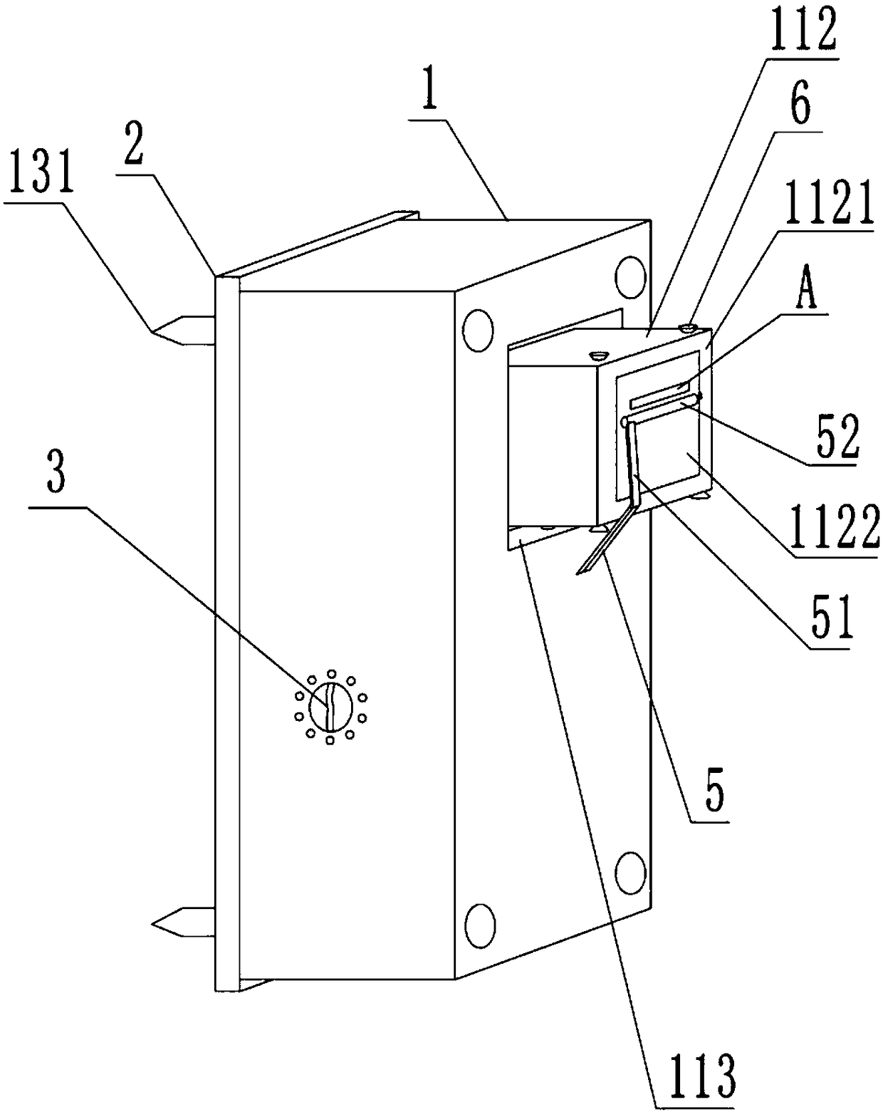
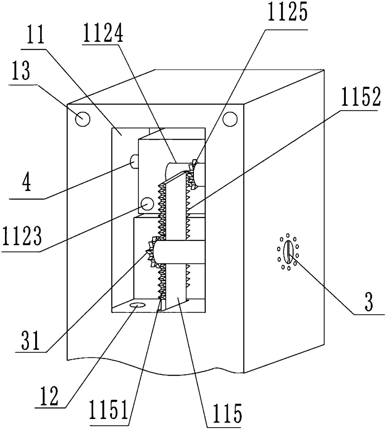
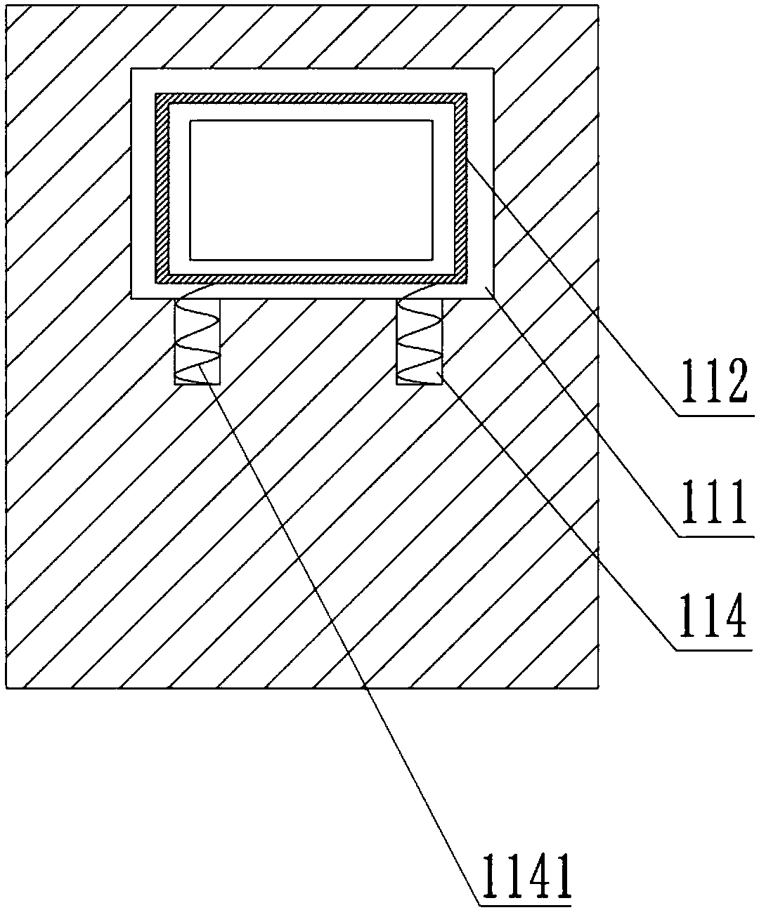
[0030] Instructions attached figure 1 , 2 , 3, 4, 5 and 6 include: outer cover 1, placement cavity 11, placement opening 111, placement box 112, dismounting panel 1121, glass 1122, wire hole 1123, fixed shaft 1124, rotating tooth 1125, placement Table 113, groove 114, tension spring 1141, vertical slide 115, first rack 1151, second rack 1152, wire hole 12, cover threaded hole 13, screw 131, cover plate 2, lock cylinder 3, power Gear 31, rotating shaft 4, support rod 5, connecting rod 51, cleaning roller 52, roller body 521, rotating column 522, handle 523, cleaning layer 524, water collection hole 525, fixing screw 6, key 7, positioning column 71, fixing Sheet 72, movable sheet 73, positioning hole 8, electric meter degree display place A.

[0031] In order to achieve the above object, the basic scheme of the present invention is as follows:

[0032] Such as figure 1...


PUM


Abstract

The invention relates to the technical field of support components, in particular to an electronic product protection structure. The electronic product protection structure comprises a housing and a cover plate. The housing is provided with a placement cavity inside and a line passing hole at the bottom. A placement opening is arranged in the wall of the placement cavity, and a placement box is arranged in the placement opening. The bottom surface of the placement opening is a placement platform, and the placement platform has a groove in which a tension spring is arranged. A vertical slide plate is also arranged in the placement cavity, and the vertical slide plate is provided with a first rack and a second rack. The outer cover is provided with a switch lock which includes a lock core and a key, and the end of the lock core is fixedly connected with a power gear. The side of the placement box outside the placement cavity is a detachable panel, the detachable panel is provided with anobservation opening, and glass is arranged in the observation opening. A line hole and a fixed shaft are arranged on the side of the placement box away from the observation opening. The fixed shaft is provided with rotating teeth meshed with the second rack. The outer cover is further provided with a cleaning part used for rubbing the surface of the glass. Through the scheme, electric meters canbe protected, and the meter reading personnel can read a meter easily.

Description

technical field [0001] The invention relates to the technical field of supporting components, in particular to an electronic product protection structure. Background technique [0002] Electronic products are related products based on electric energy. The electric meter is a commonly used electronic product. Its main function is to measure electric energy, also known as electric energy meter and electric meter. [0003] In the prior art, the electric meter is installed outdoors and indoors, and the surface of the electric meter is very easy to be stained with dust, especially when reading the degree of the electric meter, if the glass of the electric meter surface is stained with dust, people cannot see it clearly. to the degrees on the meter. In addition, for the electric meter installed outdoors, anyone can easily see the degree of the electric meter, and it is easy to steal electricity. [0004] In order to prevent electricity theft, the power supply department generall...

Claims


Application Information

Patent Timeline
IPC IPC(8): G01R11/02G01R11/04
CPCG01R11/02G01R11/04
Inventor 冯双成
Owner 山东贝斯特信息科技有限公司
Learn More