Injection molding piece clamping device

A clamping device, injection molding technology, applied in clamps, machine tools suitable for grinding workpiece edges, grinders, etc. energy saving effect

Active Publication Date: 2018-07-20
重庆雷钜电子科技有限公司
View PDF5 Cites 6 Cited by
  • Summary
  • Abstract
  • Description
  • Claims
  • Application Information

AI Technical Summary

Problems solved by technology

[0003] The purpose of the present invention is to provide a clamping device for injection molded parts to solve the problem that tubular injection molded parts are difficult to clamp and injection molded parts with different diameters need to use no clamps

Method used


Image

  • Injection molding piece clamping device
  • Injection molding piece clamping device

Examples


Embodiment Construction

[0014] The present invention will be described in further detail below by means of specific embodiments:

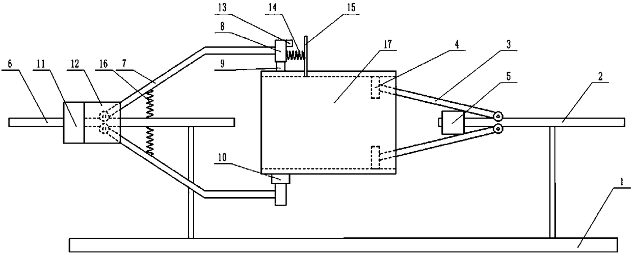
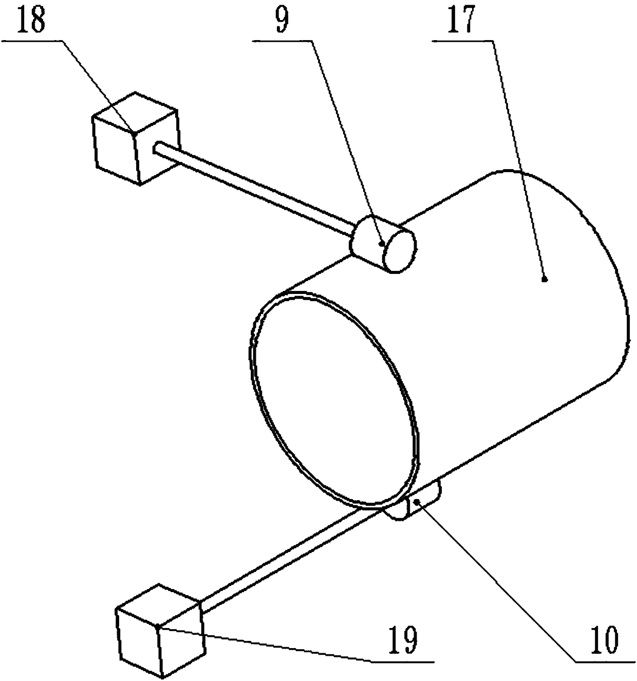
[0015] The reference signs in the drawings of the description include: frame 1, first pole 2, first bracket 3, first clamping block 4, first threaded sleeve 5, second pole 6, second bracket 7, second Two clamping blocks 8, first roller 9, second roller 10, second threaded sleeve 11, pressing piece 12, conductive block 13, insulating spring 14, electric heating blade 15, ordinary spring 16, injection molded part 17, first motor 18. The second motor 19.

[0016] Such as figure 1 , figure 2 As shown, the clamping device for injection molded parts in this embodiment includes a frame 1, a first strut 2 is provided on the right side of the frame 1, and two first brackets are respectively hinged on the upper side and the lower side of the first strut 2 3. The left end of each first bracket 3 is provided with a first clamping block 4, and the end of the first clamping block 4...


PUM


Abstract

The invention belongs to the technical field of clamping devices, and particularly discloses an injection molding piece clamping device. The injection molding piece clamping device comprises a rack, an inner ring clamping mechanism, an outer ring clamping mechanism and a flash removal mechanism; the inner ring clamping mechanism comprises a first strut, a first support is arranged on the first strut and is provided with a first clamping block, and a first threaded sleeve is arranged on the first strut; the outer ring clamping mechanism comprises a second strut, a second support is hinged to the second strut, a second clamping block is arranged on the second support, a second threaded sleeve is arranged on the second strut, and a compression sheet is arranged on the second threaded sleeve;and the flash removal mechanism comprises a first motor, a first roller, an electric conduction block, an insulation spring and an electric heating blade, the first roller is arranged on the second clamping block, the first motor is arranged on the rack, the output end of the first motor is connected with the first roller, and the insulation spring is connected with the second clamping block and the electric heating blade. The injection molding piece clamping device aims at solving the problems that pipe-shaped injection molding pieces are difficult to clamp, and injection molding pieces withdifferent diameters need to use different clamps.

Description

technical field [0001] The invention belongs to the technical field of clamping devices, and specifically discloses a clamping device for injection molded parts. Background technique [0002] Many tubular plastic products are injection molded parts by injection molding. After these injection molded parts are taken out of the injection mold, they need to be clamped by a clamping device and then transported, polished, polished and other subsequent processes. However, since the diameters of different injection molded parts are different, and the outer surface of the tubular injection molded part is round, it is difficult to clamp, and different clamps are required to clamp injection molded parts with different diameters. After the injection molded parts come out of the mold, some injection molded parts are prone to flash. There are many burrs on the injection molded parts with flash. These burrs are easy to scratch the grinding wheel or polishing wheel when grinding or polishin...

Claims


Application Information

Patent Timeline
Patent Type & Authority Applications(China)
IPC IPC(8): B25B5/14B25B5/04B25B5/10B29C37/02B24B9/20
CPCB24B9/20B25B5/04B25B5/109B25B5/147B29C37/02
Inventor 戴江毅
Owner 重庆雷钜电子科技有限公司
Why Eureka
Try Eureka