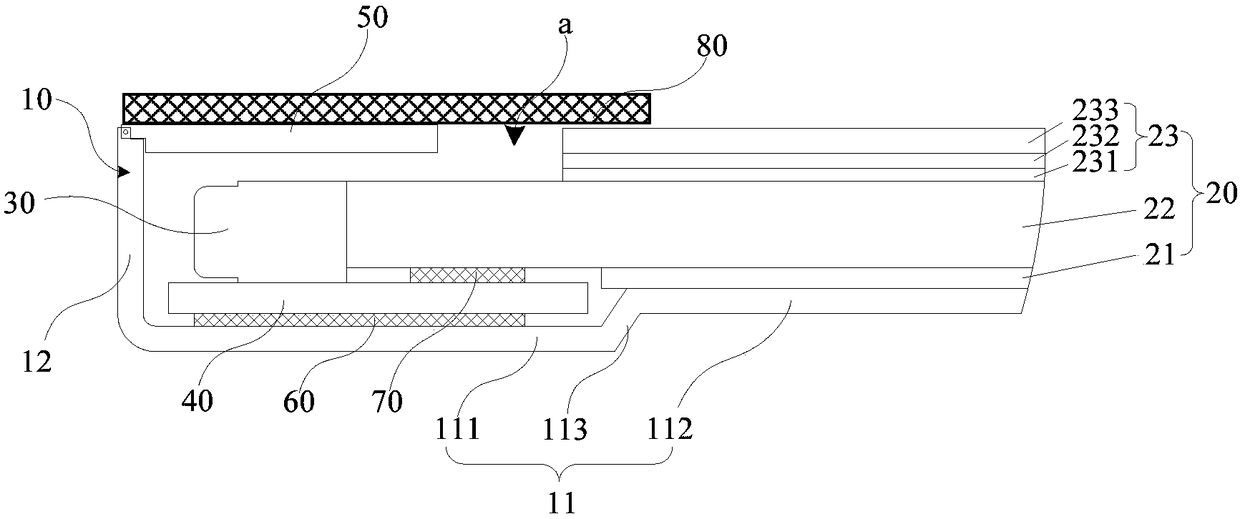
Electronic device, display assembly thereof, backlight module and assembling method thereof

A technology for backlight modules and display components, applied in optics, nonlinear optics, instruments, etc., can solve the problems of large non-display area, occupation, unfavorable narrow frame and full screen realization, and achieve the effect of ensuring stability

Active Publication Date: 2018-07-20
GUANGDONG OPPO MOBILE TELECOMM CORP LTD
View PDF7 Cites 3 Cited by
  • Summary
  • Abstract
  • Description
  • Claims
  • Application Information

AI Technical Summary

Problems solved by technology

[0003] The backlight module is an important part of an electronic device. At present, the backlight module of portable electronic devices such as smartphones usually adopts a side-entry backlight module, that is, the light emitted by the light source enters the light guide plate from the side of the light guide plate, so that the The display panel of the electronic device provides backlight. However, since the light source and some related structures of this side-type backlight module need to be arranged on the side of the light guide plate, it occupies a large non-display area, which is not conducive to narrow borders and The realization of the full screen, how to shorten the width of the backlight module in the non-display area without affecting the normal display of the backlight module and the display panel, has become the focus of attention.

Method used


Image

  • Electronic device, display assembly thereof, backlight module and assembling method thereof
  • Electronic device, display assembly thereof, backlight module and assembling method thereof
  • Electronic device, display assembly thereof, backlight module and assembling method thereof

Examples


Embodiment Construction

[0016] The technical solutions in the embodiments of the present application will be clearly and completely described below in conjunction with the drawings in the embodiments of the present application. It should be understood that the specific embodiments described here are only used to explain the present application, but not to limit the present application. In addition, it should be noted that, for the convenience of description, only some structures related to the present application are shown in the drawings but not all structures. Based on the embodiments in this application, all other embodiments obtained by persons of ordinary skill in the art without creative efforts fall within the protection scope of this application.

[0017] The terms "first", "second", etc. in this application are used to distinguish different objects, not to describe a specific order. Furthermore, the terms "include" and "have", as well as any variations thereof, are intended to cover a non-e...


PUM


Abstract

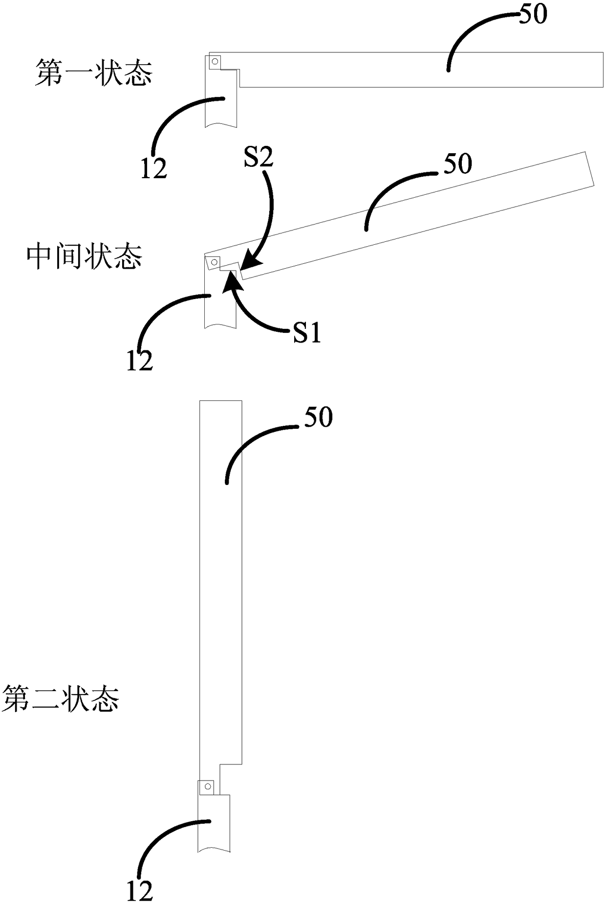
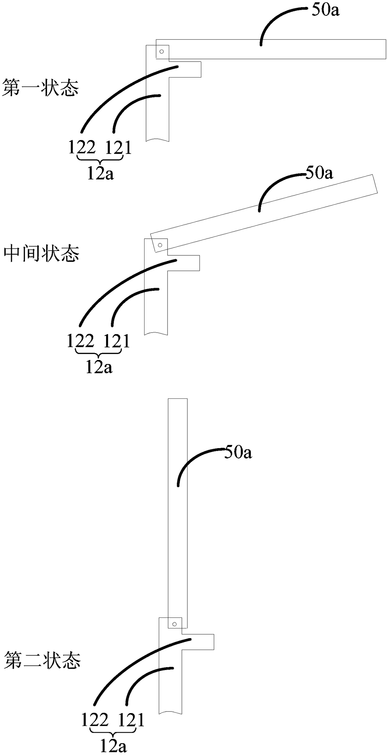
The invention discloses a backlight module. The backlight module comprises a back frame, a supporting wall, an optical assembly, a flexible circuit board and a light source, wherein the back frame comprises a bottom wall and a side wall which is in bent connection with the bottom wall, and the bottom wall and the side wall form a containing space; the supporting wall is hinged to the side wall, the supporting wall can be turned over at least in the direction close to the containing space to the first state of being parallel to the bottom wall and can be turned over at least in the direction away from the containing space to the second state of being parallel to the side wall; the optical assembly is arranged on the bottom wall and located inside the containing space; the flexible circuit board is arranged on the bottom wall and at least partially overlapped with the optical assembly; the light source is arranged on the face, away from the bottom wall, of the flexible circuit board, andthe light source is opposite to the side edge, facing the side wall, of the optical assembly. The invention further discloses an assembling method of the backlight module, a display assembly and an electronic device. In this way, on the condition that the width occupied by a non-display region of the backlight module can be lowered, the stability of a supporting display panel of the backlight module is ensured, and assembling of the backlight module is not affected.

Description

technical field [0001] The invention relates to the technical field of backlights of electronic devices, in particular to an electronic device and its display component, a backlight module and an assembly method thereof. Background technique [0002] At present, with the development of science and technology, electronic devices such as smart phones have gradually become necessities in people's lives. [0003] The backlight module is an important part of an electronic device. At present, the backlight module of portable electronic devices such as smartphones usually adopts a side-entry backlight module, that is, the light emitted by the light source enters the light guide plate from the side of the light guide plate, so that the The display panel of the electronic device provides backlight. However, since the light source and some related structures of this side-type backlight module need to be arranged on the side of the light guide plate, it occupies a large non-display are...

Claims


Application Information

Patent Timeline
Patent Type & Authority Applications(China)
IPC IPC(8): G02F1/13357
CPCG02F1/133615
Inventor 欧阳志斌
Owner GUANGDONG OPPO MOBILE TELECOMM CORP LTD
Why Eureka
Try Eureka