Wiring double-terminal automatic assembling machine and assembling process thereof

An automatic assembly machine, double-terminal technology, applied in the direction of assembly/disassembly of contacts, can solve the problems of strip breakage, easy influence, troublesome assembly of double terminals, etc., and achieve the effect of reducing the probability of strip breakage

Active Publication Date: 2019-09-06
FEILKE NANJING IND EQUIP
View PDF6 Cites 2 Cited by
  • Summary
  • Abstract
  • Description
  • Claims
  • Application Information

AI Technical Summary

Problems solved by technology

In the traditional technology, as an electrical connector for electrically connecting two electronic components, the industry is used to placing the tape reel on the discharge reel, and then directly inserting the movable end of the tape into the regular shape of the insulating body. and then break off the entire row of the conductive terminals and the material tape, the conductive terminals are arranged vertically and horizontally in the terminal grooves of the insulating body, but this conventional Operation, because the pull of the material tape is easy to cause the material tape to break, if the material tape is broken, the automatic work cannot be continued, and the processing needs to be suspended to affect the assembly efficiency, and it will be very troublesome when the double terminal needs to be assembled. affect

Method used


Image

  • Wiring double-terminal automatic assembling machine and assembling process thereof
  • Wiring double-terminal automatic assembling machine and assembling process thereof
  • Wiring double-terminal automatic assembling machine and assembling process thereof

Examples


Embodiment Construction

[0033] In the following description, numerous specific details are given in order to provide a more thorough understanding of the present invention. It will be apparent, however, to one skilled in the art that the present invention may be practiced without one or more of these details. In other examples, some technical features known in the art are not described in order to avoid confusion with the present invention.

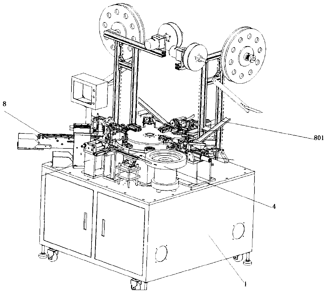
[0034] After research, it is found that in the process of automatic assembly of terminals, the general existing technology places the tape reel on the placement frame, and then the movable end is transferred to the assembly machine through the transmission component, so there will be such a problem: because the speed of assembly It is fast, so in order to ensure that the material belt can be supplied, the pulling force of the transmission component on the material belt is extremely strong, which may easily cause the material belt to break.

[0035] For this rea...


PUM


Abstract

The invention discloses a wiring double-terminal automatic assembling machine and an assembling process thereof, and belongs to the technical field of terminal assembling equipment; the wiring double-terminal automatic assembling machine comprises a rack, wherein the rack is provided with an insulator feeding mechanism, a vibrating disk, a material belt conveying mechanism, a material folding mechanism, a material belt conveying mechanism, a material folding mechanism and a clamping mechanism; the material belt conveying mechanism comprises a first fixed seat fixed on the rack, a lower mounting plate transversely arranged on the first fixed seat, a placement groove transversely formed in the lower mounting plate, a first support which is fixed on the rack and is positioned on the rear sideof the first fixed seat, a first rotary motor arranged on the first support, and a rotary gear in transmission connection with the output shaft of the first rotary motor. According to the automatic assembling machine, a U-shaped rotating gear which can be clamped with a material belt is arranged in the material belt conveying mechanism to drive the material belt to move forwards slowly in a placing groove inner seat, so that the probability of breakage of the material belt is lowered.

Description

technical field [0001] The invention belongs to the technical field of terminal assembly equipment, in particular to an automatic double-terminal assembly machine for wiring and an assembly process thereof. Background technique [0002] With the development of science and technology, the structure of electronic products is becoming more and more sophisticated, and the most functions are integrated with the smallest size as much as possible, which increases the customization requirements for circuit boards and components mounted on the circuit boards. For example, irregular wiring on the circuit board corresponds to high-frequency requirements. In the traditional technology, as an electrical connector for electrically connecting two electronic components, the industry is used to placing the tape reel on the discharge reel, and then directly inserting the movable end of the tape into the regular shape of the insulating body. and then break off the entire row of the conductive...

Claims


Application Information

Patent Timeline
IPC IPC(8): H01R43/20
CPCH01R43/20
Inventor 王四海
Owner FEILKE NANJING IND EQUIP
Why Eureka
Try Eureka