Turbine handpiece provided with needle locker

A needle locker and turbine technology, which is applied in the field of medical devices, can solve problems affecting the clamping stability of the bur, easy deformation of the U-shaped bracket, and unstable clamping of the bur, so as to reduce cleaning dead angles, fix it stably, and easily The effect of installation and removal

Inactive Publication Date: 2017-04-26
李艳霞
View PDF0 Cites 3 Cited by
  • Summary
  • Abstract
  • Description
  • Claims
  • Application Information

AI Technical Summary

Problems solved by technology

[0003] The purpose of the present invention is to provide a turbine handpiece with a needle locker. On the basis of the prior art, the connection mode between the thimble and the pillow case is improved, so as to solve the problem that the existing pins are used to connect the thimble and the sleeve. The problem of stability, and the U-shaped bracket is easy to deform, which affects the stability of the bur clamping and causes safety hazards

Method used


Image

  • Turbine handpiece provided with needle locker
  • Turbine handpiece provided with needle locker

Examples


Embodiment 1

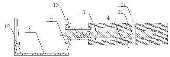
[0025] Figure 1-2 A turbine handpiece with a needle locker is shown, wherein the needle locker includes a U-shaped bracket 1, a needle sleeve 2, a thimble 3 and a sleeve 4 connected in sequence, and is characterized in that,

[0026] The sleeve 4 is radially provided with a limit hole, and the end of the thimble 3 inside the sleeve is provided with a through hole, the position of the through hole matches the position of the limit hole, and the through hole and the limit hole pass through fixed pin fixed;

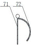
[0027] The fixing pin includes a fixing part 71 and a limiting arc 72 , the fixing part 71 is a cylinder, and the limiting arc 72 is an arc connected with one end of the fixing part 71 , and the arc is adapted to the outer surface of the sleeve 4 .

Embodiment 2

[0029] Figure 1-2 A turbine handpiece with a needle locker is shown, wherein the needle locker includes a U-shaped bracket 1, a needle sleeve 2, a thimble 3 and a sleeve 4 connected in sequence, and is characterized in that,

[0030] The sleeve 4 is radially provided with a limit hole, and the end of the thimble 3 inside the sleeve is provided with a through hole, the position of the through hole matches the position of the limit hole, and the through hole and the limit hole pass through fixed pin fixed;

[0031] The fixing pin includes a fixing part 71 and a limiting arc 72, the fixing part 71 is a cylinder, and the limiting arc 72 is an arc connected to one end of the fixing part 71, and the arc is adapted to the outer surface of the sleeve 4;

[0032] Needle grooves are provided on the outer surface of the sleeve 4, and the needle grooves are adapted to the limit arc 72;

[0033] The limit arc 72 radian 120-150°;

[0034] The diameter of the fixing pin matches the diame...

Embodiment 3

[0036] Figure 1-2 A turbine handpiece with a needle locker is shown, wherein the needle locker includes a bracket 1, a thimble 3, a needle sleeve 2, a fixing needle and a sleeve 4, wherein,

[0037] The bracket 1 is U-shaped, and a round hole 13 is arranged on one side wall, and a needle sheath 2 is set inside the round hole 13;

[0038] The side wall at one end of the thimble 3 is provided with a radially outward protrusion, the diameter of the protrusion is adapted to the inner diameter of the needle sleeve 2, the thimble 3 passes through the needle sleeve so that the other end of the thimble 3 is located in the sleeve 4, the sleeve 4 The inner wall of the cylinder 4 is provided with an annular limiting part, and the diameter of the thimble 3 is adapted to the inner diameter of the annular limiting part;

[0039] The sleeve 4 is provided with a limiting hole in the radial direction, and the other end of the thimble 3 is provided with a through hole in the radial direction,...


PUM


Abstract

The invention discloses a turbine handpiece provided with a needle locker, which comprises a support, an ejector needle, a needle guard and a sleeve. Mutually adaptive through holes are formed in the radial direction in the tail end of the ejector needle and the sleeve; a fixing needle is inserted into the through holes for fixing the ejector needle and the sleeve, and comprises a fixing part and a limiting arc, the fixing part is a cylinder, the limiting arc is an arc connected with one end of the fixing part, and the arc is matched with the outer surface of the sleeve. According to the invention, the ejector needle and the sleeve are connected by utilizing the fixing needle, all that is needed for connection is to align the through hole in the ejector needle to the through hole in the sleeve, and then insert the fixing part of the fixing needle into the through holes, the installation is convenient and simple, and the fixation is relatively stable, so that conditions of misplacement and ejector needle deflection are avoided; the ejector needle comprises the limiting arc, the fixing part inserted into the through holes can sleeve the sleeve to prevent the fixing needle from falling off and causing a potential safety hazard; a needle groove matched with the limiting arc is arranged on the sleeve and can hide the limiting arc in the needle groove without influencing the assembly of other parts in the handpiece.

Description

technical field [0001] The invention relates to the field of medical instruments, in particular to a turbine handpiece with a needle locker. Background technique [0002] The turbine handpiece uses compressed gas to drive the movement to rotate at a high speed, thereby driving the bur with specific functions, so that the dentist can drill and grind the patient's teeth or dentures. According to the different ways of clamping the bur, the turbo handpiece can be divided into a lock pin type and a push type. The lock pin type turbo handpiece locks the bur on the turbo handpiece through a needle locker. The existing needle locker mainly fixes the thimble and the sleeve through pins, but due to the small size and fine structure of the handpiece of the turbine handpiece, it is easy to cause the thread to be misaligned when connected with a pin, resulting in the thimble not being aligned with the needle sleeve and the sleeve. If the central line is set, it is easy to cause the clam...

Claims


Application Information

Patent Timeline
Patent Type & Authority Applications(China)
IPC IPC(8): A61C3/02A61C1/05A61C1/08
CPCA61C3/02A61C1/05A61C1/082
Inventor 李艳霞
Owner 李艳霞
Why Eureka
Try Eureka