Electronic terminal

An electronic terminal and circuit board technology, applied in the direction of antenna equipment with additional functions, can solve the problems of occupying antenna space, consuming traffic, increasing costs, etc., and achieving the effect of increasing hardware costs and traffic tariffs

Inactive Publication Date: 2018-07-20
SAMSUNG TIANJIN MOBILE DEV CENT +1
View PDF0 Cites 0 Cited by
  • Summary
  • Abstract
  • Description
  • Claims
  • Application Information

AI Technical Summary

Problems solved by technology

[0002] At present, due to the length of the FM antenna, most electronic terminals do not have a built-in FM antenna. Generally, earphone cables are used as FM antennas. Therefore, these electronic terminals must be plugged into earphones to listen to FM, which is not convenient enough.
Some electronic terminals have a built-in FM antenna, but this requires a certain amount of antenna space and additional costs
[0003] In addition, you can also listen to FM with the help of various existing FM application software, but this requires traffic and generates a certain amount of traffic charges

Method used


Image

  • Electronic terminal
  • Electronic terminal

Examples


Embodiment Construction

[0017] Exemplary embodiments of the present invention will now be described in detail, and examples of the exemplary embodiments of the present invention are shown in the accompanying drawings. The embodiments are described below to explain the present invention by referring to the figures. However, the present invention can be implemented in many different forms and should not be construed as being limited to the exemplary embodiments set forth herein. On the contrary, these embodiments are provided so that this disclosure will be thorough and complete, and these embodiments will fully convey the scope of the present invention to those skilled in the art.

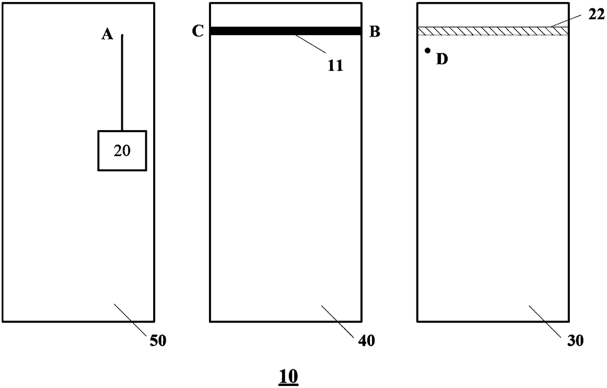
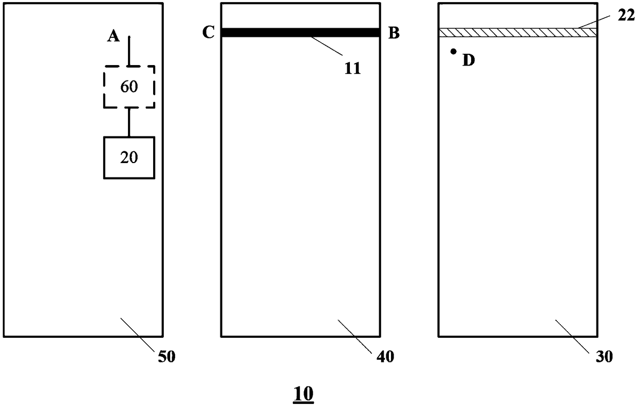
[0018] figure 1 It shows a schematic structural diagram of an electronic terminal provided with an FM antenna according to an exemplary embodiment of the present invention. Refer below figure 1 The composition and working principle of the FM antenna of the electronic terminal 10 will be introduced in detail. As an example, ...


PUM


Abstract

The invention provides an electronic terminal. The electronic terminal includes an FM antenna and an FM reception module arranged on a circuit board of the electronic terminal. The electronic terminalis characterized in that a metal housing of the electronic terminal and a metal part in a circuit board support of the electronic terminal are taken as the FM antenna, wherein one position of the metal part in the circuit board support of the electronic terminal is electrically connected to the metal housing and the other position of the metal part in the circuit board support of the electronic terminal is electrically connected to the FM reception module. By adopting the electronic terminal provided by the invention, no external pull rod antenna is needed and no built-in FM antenna is required for implementing high-flexibility reception and emission of FM signals. Besides, by using the prior structure of the electronic terminal, the material cost of FM antenna design is saved.

Description

Technical field [0001] The present invention generally relates to the field of frequency modulation (FM) antenna design, and more specifically, to an electronic terminal that uses the existing structure of the electronic terminal to form an FM antenna. Background technique [0002] At present, due to the length of the FM antenna, most electronic terminals do not have a built-in FM antenna, and generally use a headphone cable as an FM antenna. Therefore, these electronic terminals must be plugged in to listen to FM, which is not convenient. Some electronic terminals have built-in FM antennas, but this requires a certain amount of antenna space and adds additional costs. [0003] In addition, you can also listen to FM with the help of various existing FM application software, but this requires traffic consumption and generates certain traffic charges. Summary of the invention [0004] The purpose of the exemplary embodiments of the present invention is to propose an electronic termin...

Claims


Application Information

Patent Timeline
Patent Type & Authority Applications(China)
IPC IPC(8): H01Q1/44
CPCH01Q1/44
Inventor 崔明权李健阎辰
Owner SAMSUNG TIANJIN MOBILE DEV CENT
Why Eureka
Try Eureka