Method for the operation of an antenna group having a plurality of transmitters and a plurality of receivers and associated apparatus

Inactive Publication Date: 2010-12-07
KARLSRUHER INST FUR TECH
View PDF4 Cites 54 Cited by
  • Summary
  • Abstract
  • Description
  • Claims
  • Application Information

AI Technical Summary

Benefits of technology

[0009]Hence, in the proposed method, an amplitude weighting is not, as previously usual, applied to the transmitters and / or the receivers. The amplitude weighting is rather applied to all combinations of transmitters and receivers, and hence receive signals, which are evaluated during processing. Therefore, for selection of the amplitude weighting, not only M+N but M·N degrees of freedom are available. Thereby, the dynamic range for multi-transmitter-multi-receiver antenna groups with only a small number of transmitters and receivers can also be increased considerably. The method and the associated apparatus hence allow the utilization of a multi-transmitter-multi-receiver system for digital beamforming, which, at the same time, by means of the utilization of as few transmitters and receivers as possible, can achieve a high angle resolution, and on the other hand, a high dynamic range.
[0016]With the amplitude weighting of the M·N receive signals, preferably in the form of a weighting matrix, M·N degrees of freedom are achieved for selection of the amplitude factors. Hence, there are considerably more degrees of freedom available compared to the determination of two separate weighting vectors for the M transmitters and the N receivers with M+N degrees of freedom, as this is known for the typical application of weighting functions. The method hence allows a substantially higher flexibility for the determination of the weighting function, and thereby a higher dynamic range at angle measurement. Hence, with the proposed method, weighting functions, which offer a high dynamic range but until now can only be used with a high number of L elements, i.e. transmitters and / or receivers, can now be used also with 2·√L elements. Through this, antennas, and hence hardware cost, can be saved.

Problems solved by technology

Such amplitude weighting, however, achieves the desired result only if a high number of receivers is available.

Method used


Image

  • Method for the operation of an antenna group having a plurality of transmitters and a plurality of receivers and associated apparatus
  • Method for the operation of an antenna group having a plurality of transmitters and a plurality of receivers and associated apparatus
  • Method for the operation of an antenna group having a plurality of transmitters and a plurality of receivers and associated apparatus

Examples


Embodiment Construction

[0007]The object is achieved by means of the method and the apparatus according to the patent claims 1 and 8. Advantageous embodiments of the method and the apparatus are subject matter of the sub-claims or can be learned from the following description and the exemplary embodiment.

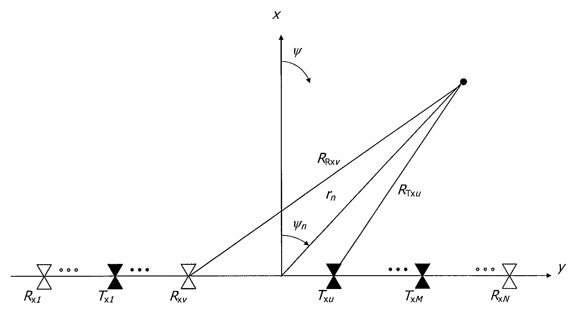
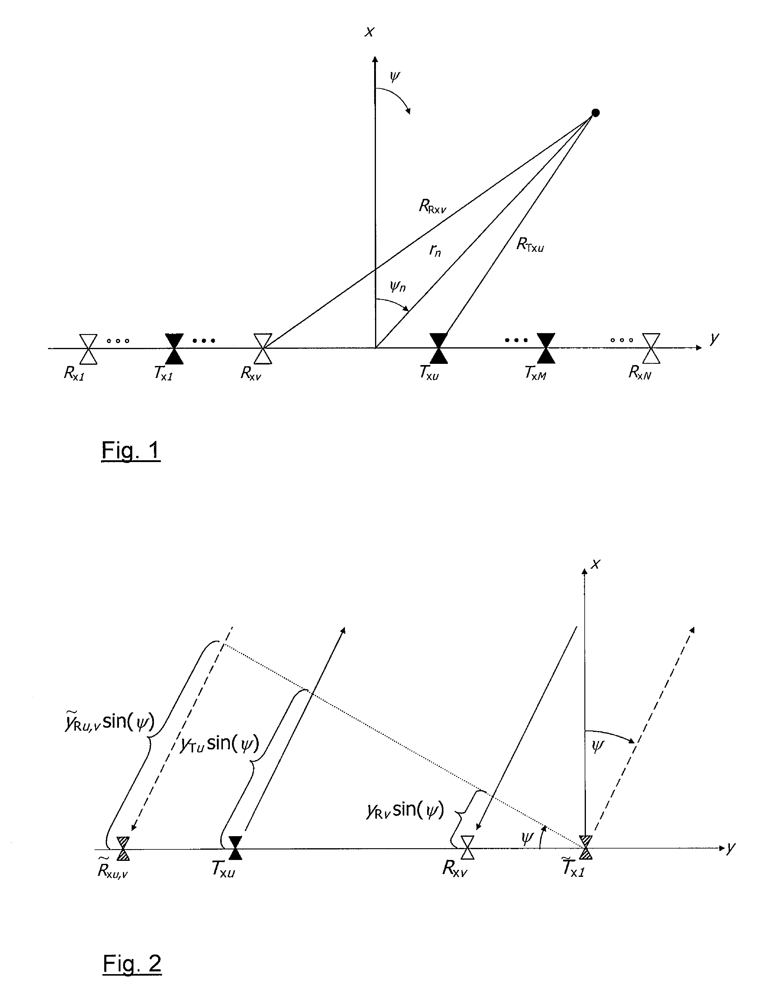
[0008]In the proposed method for the operation of an antenna system or an antenna group, respectively, comprising M≧2 transmitter and N≧2 receiver, a coherent transmit signal is transmitted in a known manner in a transmit-receive-cycle via each of the M transmitters to the area to be monitored, and for each transmit signal a coherent receive signal from the area is recorded by the N receivers, wherein M·N receive signals are obtained. To each receive signal, a combination of the respective transmitting transmitter, for which the receive signal is obtained, and the respective receiving receiver, which receives this receive signal, is allocated so that the M·N receive signals can be processed subsequently by...


PUM


Abstract

The present invention relates to a method for the operation of an antenna group (1) having M≧2 transmitters and N≧2 receivers (3) for the digital beamforming. In the method, a coherent transmit signal is transmitted in a transmit-receive-cycle via each of the M transmitters (2) into an area to be monitored, and a coherent receive signal from the area is recorded by each of the N receivers (3) for each transmit signal so that M·N receive signals are obtained. To each receive signal, a combination of the respective transmitting transmitter (2) and the respective receiving receiver (3) is allocated. The M·N receive signals are processed by means of digital beamforming to obtain spatial information about objects in the area to be monitored. In the method, each of the M·N receive signals is multiplied during processing by an amplitude factor which is individually allocated to the respective combination of transmitter (2) and receiver (3), wherein the amplitude factors are selected such that an increase of the signal dynamic range at the digital beamforming is achieved. The method and the apparatus formed for the execution of the method allow a high angle resolution and, at the same time, a high signal dynamic range.

Description

TECHNICAL FIELD OF APPLICATION[0001]The present invention relates to a method for the operation of an antenna group having M≧2 transmitters and N≧2 receivers, in which a coherent transmit signal is transmitted in a transmit-receive-cycle via each of the M transmitters into an area to be monitored, and a coherent receive signal from the area is recorded by each of the N receivers for each transmit signal, wherein M·N receive signals are obtained, and to each of the receive signals a combination of the respectively transmitting transmitter and the respectively receiving receiver is assigned, and in which the M·N receive signals are processed by means of digital beamforming to obtain spatial information about the objects in the area to be monitored. The invention relates in addition to an apparatus for radar monitoring of an area, which utilizes the method.[0002]The method and the apparatus utilize the technique of digital beamforming (DBF: Digital Beamforming), in which for each recei...

Claims


Application Information

Patent Timeline
Patent Type & Authority Patents(United States)
IPC IPC(8): H01Q3/00G01S13/931
CPCG01S7/2813G01S7/288G01S13/42G01S13/931G01S2013/0245
Inventor WIESBECK, WERNERSCHULER, KARIN
Owner KARLSRUHER INST FUR TECH
Why Eureka
Try Eureka