Bed for children
A technology for children's beds and bed boards, which is applied in the field of children's beds, can solve problems such as troublesome operation, and achieve the effect of convenient operation
- Summary
- Abstract
- Description
- Claims
- Application Information
AI Technical Summary
Problems solved by technology
Method used
Image
Examples
Embodiment 1
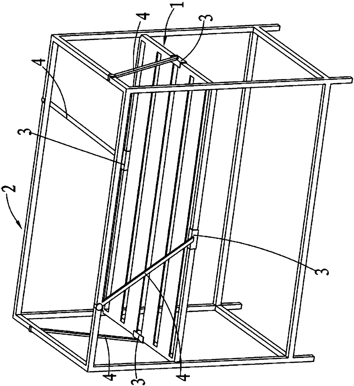
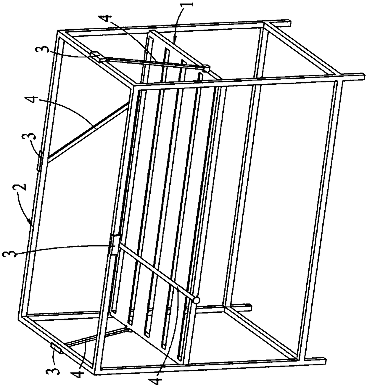
[0024] Embodiment one: as attached figure 1 , attached figure 2 As shown, a children's bed includes a side wall with a side wall space, and a bed board 1 located in the side wall space.
[0025] The side wall includes a side wall frame 2 , and some side walls also include a cloth cover wrapped on the side wall frame 2 . The bed board 1 is arranged in the side wall space so as to move up and down, and a lifting mechanism for driving the bed board 1 to move up and down relative to the side wall frame 2 is provided between the side wall frame 2 and the bed board 1. The children's bed also includes a locking mechanism for locking A locking mechanism for the relative position between the side frame 2 and the bed board 1.
[0026] The side wall frame 2 is surrounded by four side wall components. The top view of the side wall frame 2 is a quadrangle, and the bed board 1 is a quadrangle accordingly. It is also possible for the side frame 2 to be made circular in plan view.
[002...
Embodiment 2
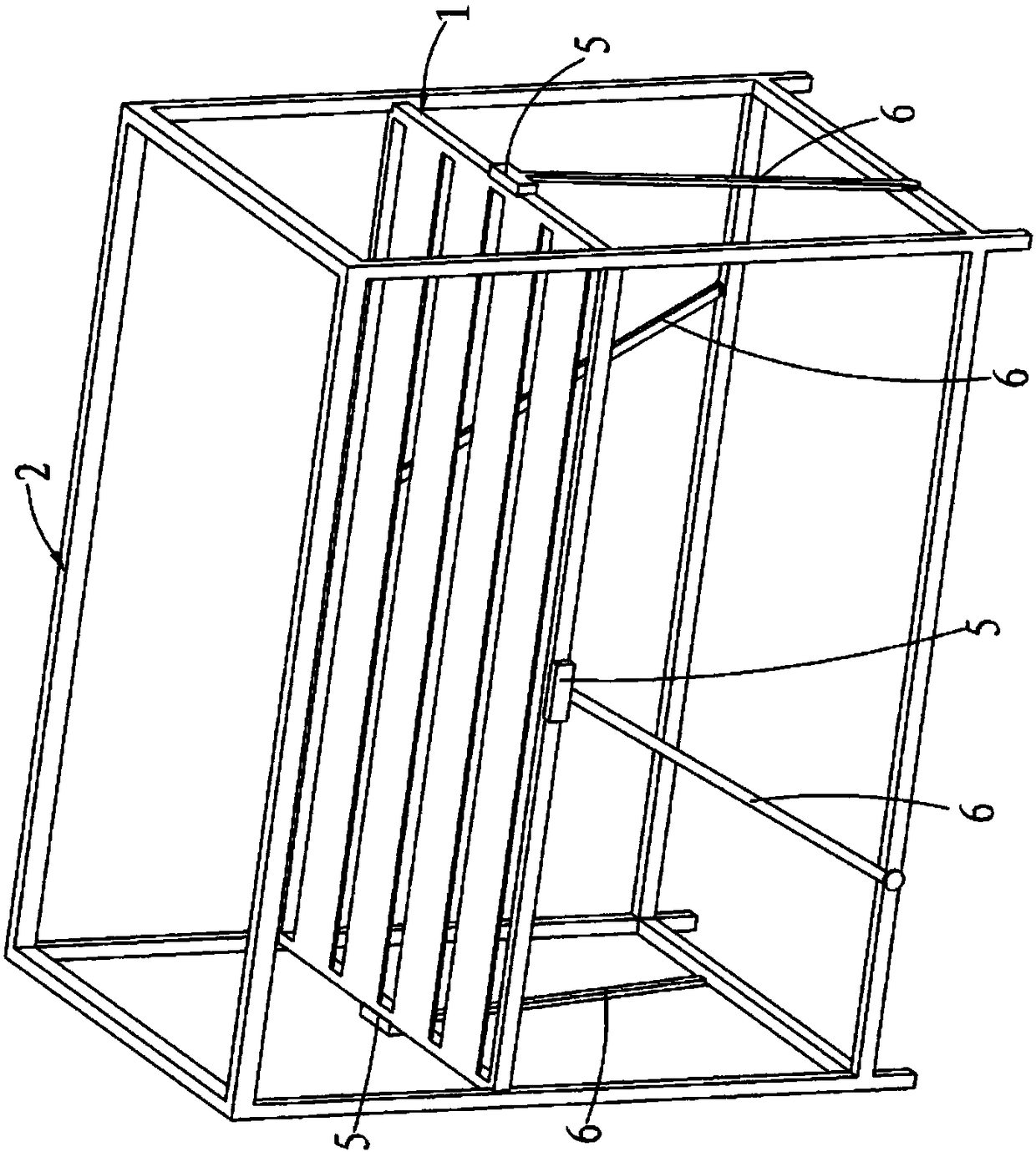
[0030] Embodiment two: as attached image 3 , the difference from Embodiment 1 is that each group of linkage mechanisms includes a second sliding member 5 which is slidably arranged on the bed board 1 along the horizontal straight direction, and an inclined second sliding member 5 which is rotatably connected at one end. The other end of the connecting rod 6 and the second connecting rod 6 are rotatably connected with the lower part of the side frame 2 . The locking mechanism can be arranged between the second sliding member 5 and the bed board 1 , and can also be arranged at the rotational connection between the lower end of the second connecting rod 6 and the lower part of the side frame 2 .
[0031] The link mechanism can also be another connection method, such as attached Figure 4 As shown, each set of link mechanisms includes a second sliding member 5 slidably disposed on the lower part of the side frame 2 along a horizontal straight line, and an inclined second connect...
Embodiment 3
[0032] Embodiment three: as attached Figure 5 As shown, the difference from Embodiment 1 is that the lifting mechanism includes two sets of linkage mechanisms, each set of linkage mechanisms are respectively located on opposite sides of the bed board 1, and each set of linkage mechanisms includes one end and the bed board 1 through the first The rotating shaft 11 is rotatably connected to the first strut 7 which is arranged obliquely, the second strut 8 which is rotatably connected to the bottom of the side frame 2 through the second rotating shaft 12 at one end, and the second strut 8 which is obliquely arranged at one end and the bed board 1 through the third The rotating shaft 13 is rotatably connected to the third strut 9 which is arranged obliquely; The other ends of the two struts 8 are rotatably connected, and the other end of the third strut 9 is rotatably connected with the other end of the fourth strut 10 . The locking mechanism can be arranged at any rotating join...
PUM
 Abstract
Description
Claims
Application Information
 - R&D Engineer
- R&D Manager
- IP Professional
- Industry Leading Data Capabilities
- Powerful AI technology
- Patent DNA Extraction
Browse by: Latest US Patents, China's latest patents, Technical Efficacy Thesaurus, Application Domain, Technology Topic, Popular Technical Reports.
© 2024 PatSnap. All rights reserved.Legal|Privacy policy|Modern Slavery Act Transparency Statement|Sitemap|About US| Contact US: help@patsnap.com


