
Stamping device for auto parts

A technology for auto parts and stamping devices, applied in the field of stamping devices for auto parts, can solve the problems of low production efficiency, poor forming quality, inconvenient discharging, etc., and achieve the effects of simple structure, easy operation and easy discharging.

Active Publication Date: 2019-02-26
沛县奔腾工贸有限公司
View PDF6 Cites 0 Cited by
  • Summary
  • Abstract
  • Description
  • Claims
  • Application Information

AI Technical Summary

Problems solved by technology

[0006] The purpose of the present invention is to provide a stamping device for auto parts to solve the problems of low production efficiency, poor molding quality, inconvenient discharging and potential safety hazards

Method used


Image

  • Stamping device for auto parts

Examples


Embodiment Construction

[0018] The present invention will be described in further detail below by means of specific embodiments:

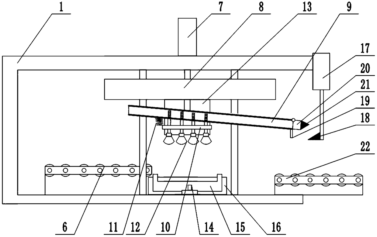
[0019] Instructions attached figure 1 The reference signs in include: frame 1, feeding mechanism 6, second cylinder 7, fixed plate 8, inclined plate 9, support plate 10, spring 11, suction cup 12, upper stamping die 13, third cylinder 14, clamping plate 15. The lower stamping die 16, the first cylinder 17, the second wedge 18, the block 19, the cover 20, the first wedge 21, and the discharge conveyor belt 22.

[0020] Such as figure 1 As shown, a stamping device for auto parts includes a frame 1 and a fixed plate 8 slidingly connected with the frame 1. A second cylinder 7 that drives the fixed plate 8 to move up and down is installed on the frame 1. The lower end of the fixed plate 8 is The upper stamping die 13 is fixedly connected, and the lower end of the fixed plate is also connected with a sloping plate through a connecting piece. The frame is provided with a slide...


PUM


Abstract

The invention belongs to the technical field of production equipment for vehicle parts and particularly discloses a stamping device for vehicle parts. The stamping device for vehicle parts comprises arack and a fixing board; the rack is provided with a drive mechanism; the fixing board is connected with an upper stamping mold and an inclined board; the inclined board is of a hollow structure; theupper inclined end of the inclined board is closed, and a cover is hinged to the lower inclined end of the inclined board; the cover is provided with a first wedge block; a first cylinder is fixed tothe rack and connected with a second wedge block; the upper portion of the inclined board is in sliding connection with a suction and pressing device; the suction and pressing device comprises a plurality of hollow columns and a suction cup; the hollow columns are provided with a supporting board; one side of the supporting board is connected with the inclined board through a spring; a check block is arranged on the lower portion of the inclined board; a lower stamping mold is arranged under the suction cup; a feeding mechanism is arranged on one side of the lower stamping mold; and a discharging conveyor belt is arranged on the other side of the lower stamping mold and located under the lower inclined end of the inclined board. By adoption of the technical scheme, the problems that the production efficiency is low, the forming quality is poor, discharging is inconvenient and potential safety hazards exist are solved.

Description

technical field [0001] The invention belongs to the technical field of auto parts production equipment, in particular to a stamping device for auto parts. Background technique [0002] With the continuous development of social economy and the continuous improvement of people's living standards, the number of private cars is increasing, and various parts and components are used in the production process of cars, and the parts of cars are mostly made of metal The material is directly stamped. In this way, a stamping machine must be used in the production process of auto parts. However, the stamping machines currently used to produce auto parts have the following disadvantages: [0003] 1. At present, when the stamping machine used to produce auto parts stamps the workpiece, it needs to manually place the workpiece on the stamping die, which seriously affects the production efficiency of auto parts, and there is still a large safety hazard when workers operate Hidden danger; ...

Claims


Application Information

Patent Timeline
Patent Type & Authority Patents(China)
IPC IPC(8): B21D43/00B21D45/04
CPCB21D43/003B21D45/04
Inventor 杨会
Owner 沛县奔腾工贸有限公司
Learn More