Rubber hot press forming die

A hot press molding and mold technology, applied in the field of rubber molding, can solve the problems of molding needle position deviation, troublesome disassembly and replacement, friction loss between molding needle and mold, etc.

Active Publication Date: 2021-08-24
重庆富胜科技有限公司
View PDF10 Cites 0 Cited by
  • Summary
  • Abstract
  • Description
  • Claims
  • Application Information

AI Technical Summary

Problems solved by technology

[0005] In the above scheme, molding is used to form rubber parts. The molding needle is fixed with the mold by screws. It is troublesome to disassemble and replace the molding needle (plastic model). During the frequent replacement of the molding needle, friction between the molding needle and the mold will occur. Loss, causing the position of the molding needle to shift, resulting in defective rubber products

Method used


Image

  • Rubber hot press forming die
  • Rubber hot press forming die
  • Rubber hot press forming die

Examples


Embodiment 1

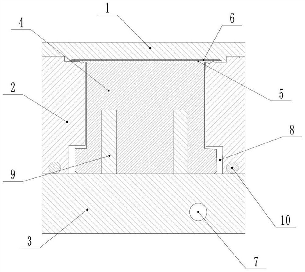
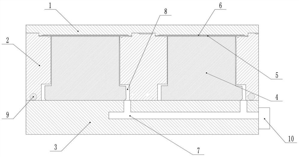
[0023] as attached figure 1 As shown, a mold for rubber thermocompression molding includes an upper mold 1, a middle mold 2, a cylindrical insert 4 and a lower mold 3, and guide grooves are provided at the edges of the upper mold 1, the middle mold 2 and the lower mold 3, Provides easy access to stacked molds and prevents confusion in mold orientation. The corresponding end of the upper mold 1 and the middle mold 2 is provided with an upper molding cavity, and the corresponding end of the middle mold 2 and the upper mold 1 is provided with a lower molding cavity. The positions of the lower molding cavity and the upper molding cavity are matched. Used together to make rubber products6. The number of upper molding cavities is 12, the number of lower molding cavities is 12, and the number of lower molding cavities corresponds to the number of upper molding cavities. It can complete the production of multiple rubber products at the same time, improving the production efficiency....

Embodiment 2

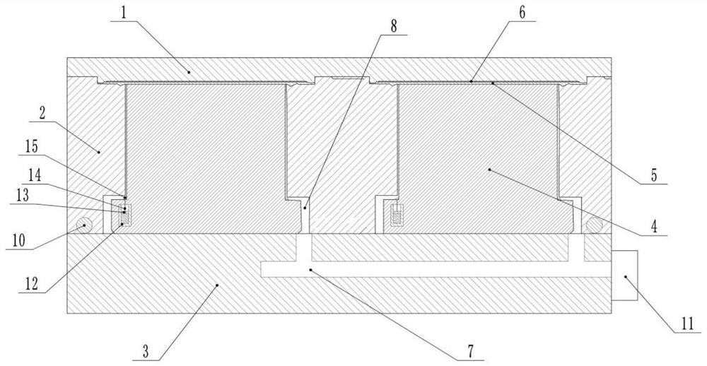
[0030] The difference between this embodiment and Embodiment 1 is that a negative pressure compensation mechanism is provided on the cylindrical insert 4, as shown in the attached image 3As shown, the negative pressure compensation mechanism includes a cylinder 12 and a sealing rubber ring 15, the cylinder 12 is fixedly connected with the cylindrical insert 4 through bolts, the cylinder 12 is located in the cylindrical insert 4, and the cylinder 12 is filled with a working medium, which is chloropropane , Chloropropane is a colorless liquid with the smell of chloroform, and the boiling point of chloropropane is 47°C. The cylinder 12 is provided with a piston 13, and a moving rod 14 is welded on the piston 13. The moving rod 14 is slidably arranged on the inner wall of the cylindrical insert 4. The moving rod 14 is welded to the cylinder 12 through a spring, and the spring can make the moving rod 14 recover quickly. In the original position, the moving rod 14 bolts are connect...


PUM


Abstract

The invention belongs to the field of rubber forming, and particularly relates to a rubber hot press forming die which comprises an upper die, a middle die, a lower die and a cylindrical insert. Upper forming cavities are formed in the end, corresponding to the middle die, of the upper die; and lower forming cavities are formed in the end, corresponding to the upper die, of the middle die. Rubber gaskets for sealing the middle die and the lower die is arranged between the lower die and the middle die, a cylindrical insert is fixedly connected with the lower die through a positioning groove and a positioning column, gaps are formed between the cylindrical insert and the middle die and communicate with the lower forming cavities, an air suction channel is formed in the lower die, one end of the air suction channel communicates with the gaps, and the other end of the air suction channel communicates with an air pump. According to the scheme, a plastic model is fixed by negative pressure of the gaps and the air suction channel and is prevented from moving to cause bad products, so that the production efficiency of rubber products is improved; and meanwhile, gas in the forming cavities is reduced, bubbles in the rubber products are reduced, and the rubber forming effect is good.

Description

technical field [0001] The invention belongs to the field of rubber molding, and in particular relates to a rubber hot-press molding mold. Background technique [0002] Rubber (Rubber) refers to a highly elastic polymer material with reversible deformation. It is elastic at room temperature, can produce large deformation under a small external force, and can return to its original shape after the external force is removed. Rubber is a completely amorphous polymer, its glass transition temperature (T g) is low, and its molecular weight is often very large, greater than hundreds of thousands. [0003] Early rubber was latex from plants such as rubber trees and rubber grasses, which were processed into materials that were elastic, insulating, impermeable to water and air. It is a high elastic polymer compound. Rubber is divided into two kinds of natural rubber and synthetic rubber. Natural rubber is processed by extracting gum from rubber trees, rubber grass and other plants...

Claims


Application Information

Patent Timeline
Patent Type & Authority Applications(China)
IPC IPC(8): B29C43/36B29C33/30
CPCB29C43/36B29C33/30
Inventor 李金祥吴宗穆
Owner 重庆富胜科技有限公司
Why Eureka
Try Eureka