Nap removal device for towel decorating machine

A technology for printing machines and towels, which is applied to the general parts of printing machinery, printing machines, printing, etc. It can solve the problems of blocking the flower position of the screen, affecting production efficiency, increasing costs, etc., and achieves good hair removal effect and simple structure , the effect of easy operation

Pending Publication Date: 2018-07-24
HAINING KUCAI DIGITAL TECH CO LTD
View PDF0 Cites 4 Cited by
  • Summary
  • Abstract
  • Description
  • Claims
  • Application Information

AI Technical Summary

Problems solved by technology

[0002] The towel printing machine is the main production equipment in the towel manufacturing industry. Although most of the various types of towel printing machines currently on the market are economical and practical, various advanced technologies at home and abroad also make the staff more accurate in operation, but Because the fluff attached to the blanks such as towels and bath towels is manually shaken off, or the remaining floating hairs will stick to the printing screen during the printing process, blocking the flower position of the screen and causing defective products, so generally When the printing machine is running for a few hours, it will be shut down for a period of time to clean up the floating wool that sticks to the net, which seriously affects the production efficiency
[0003] During the use of the existing hair removal device, the hair removal effect is not good because the scraper is not sharp, and the corresponding fibers will be involved. Therefore, the scraper needs to be replaced frequently, which increases the cost to a certain extent. It is large, and corresponding devices are required to process the cut materials, which increases the production cost and the effect is poor. Therefore, a hair removal device for towel printing machines is needed to improve the above problems

Method used


Image

  • Nap removal device for towel decorating machine
  • Nap removal device for towel decorating machine
  • Nap removal device for towel decorating machine

Examples


Embodiment Construction

[0020] The technical solutions in the embodiments of the present invention will be clearly and completely described below in conjunction with the accompanying drawings in the embodiments of the present invention. Obviously, the described embodiments are only some of the embodiments of the present invention, not all of them. Based on The embodiments of the present invention and all other embodiments obtained by persons of ordinary skill in the art without making creative efforts belong to the protection scope of the present invention.

[0021] see Figure 1-3 , the present invention provides a technical solution:

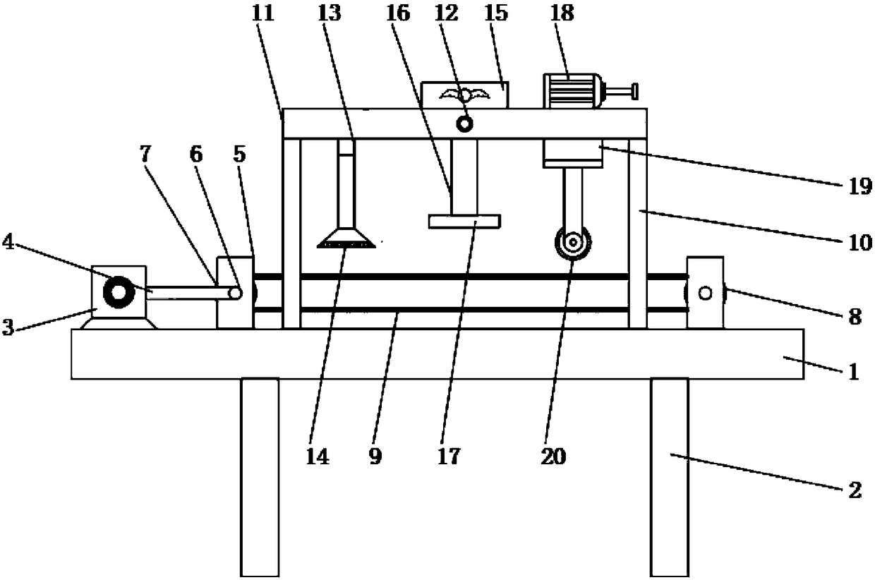
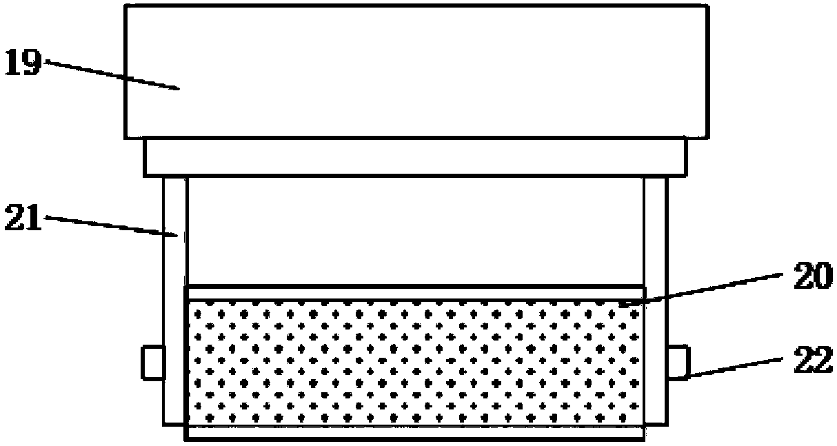
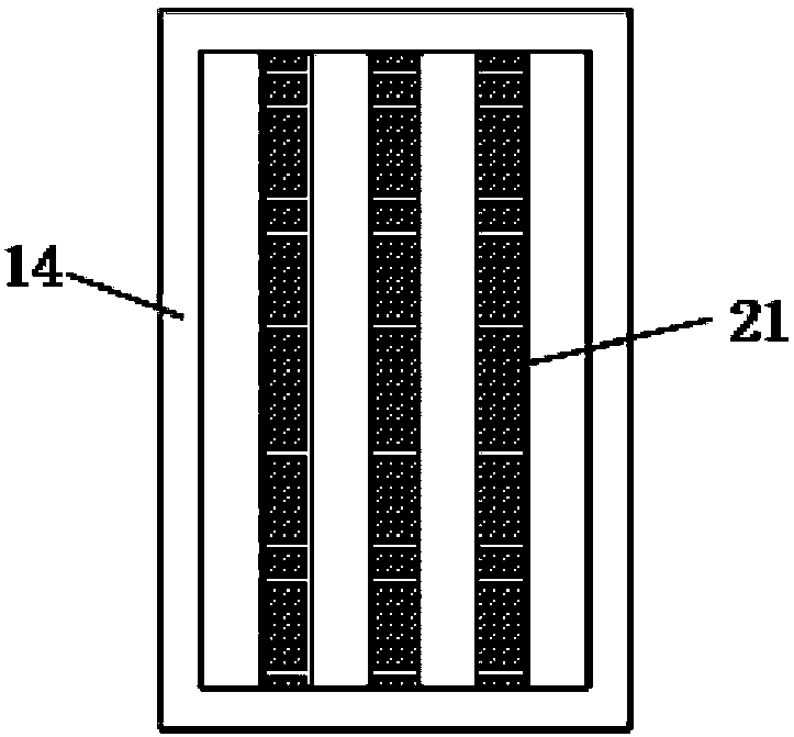
[0022] A hair removal device for a towel printing machine, comprising a console 1, a drive motor 3, a positioning plate 11, a blower 15, and an electro-hydraulic cylinder 18. A bracket 2 is installed at the bottom of the console 1. A fixed plate 5 is provided, and the center of the fixed plate 5 is provided with a first rotating shaft 6, the outer ring of the first ...


PUM


Abstract

The invention relates to the technical field of nap removal devices, and particularly relates to a nap removal device for a towel decorating machine. The nap removal device comprises an operating platform, a driving motor, a positioning plate, a blast blower and an electric hydraulic cylinder, wherein a bracket is mounted at a bottom end of the operating platform; fixing plates are arranged on a left side and a right side of an upper end of the operating platform; a first rotating shaft is arranged at the center of the fixing plate; a driving wheel is arranged on an outer ring of a first rotating shaft on the left side; a driven wheel is arranged on the outer ring of the first rotating shaft on the right side; the driving motor is mounted on the left side of the driving wheel; a connectingrod is arranged on the driving motor; the other end of the connecting rod is connected to the first rotating shaft on the left side; a conveyor belt is connected between the driving wheel and the driven wheel; upright columns are mounted on an upper end surface of the operating platform; the positioning plate is mounted between the upright columns; and a control switch is arranged at the center of the front surface of the positioning plate. The nap removal device has advantages of relatively good integral stability, simple structure, relatively good nap removal effect, low cost and convenientoperation, and has a certain promotion value.

Description

technical field [0001] The invention relates to the technical field of hair removal devices, in particular to a hair removal device for a towel printing machine. Background technique [0002] The towel printing machine is the main production equipment in the towel manufacturing industry. Although most of the various types of towel printing machines currently on the market are economical and practical, various advanced technologies at home and abroad also make the staff more accurate in operation, but Because the fluff attached to the blanks such as towels and bath towels is manually shaken off, or the remaining floating hairs will stick to the printing screen during the printing process, blocking the flower position of the screen and causing defective products, so generally When the printing machine was running for several hours, it was shut down for a period of time to clean up the floating wool sticking to the net, which seriously affected the production efficiency. [00...

Claims


Application Information

Patent Timeline
IPC IPC(8): B41F23/04B41F23/00
CPCB41F23/002B41F23/04
Inventor 王继钢
Owner HAINING KUCAI DIGITAL TECH CO LTD
Why Eureka
Try Eureka