Supercharge Your Innovation With Domain-Expert AI Agents!

Spring lock

A ball lock and lock shell technology, which is applied in the field of locks, can solve the problems of poor combination of the ball lock and the combination lock, complicated parts and components, and easy conflict, and achieves the effect of simple and practical structure, low production cost, and improved use effect.

Pending Publication Date: 2018-07-24
深圳市诺尔巴克科技有限公司
View PDF0 Cites 0 Cited by
  • Summary
  • Abstract
  • Description
  • Claims
  • Application Information

AI Technical Summary

Problems solved by technology

When the correct key is put in, each marble is pushed to the same height, and the lock cylinder is released and can be rotated, thereby driving the square shaft to rotate to realize unlocking. However, the existing pin locks are usually used in conjunction with combination locks. Direct unlocking, on the other hand, you can use the motor to drive the square shaft to rotate to unlock by inputting the password. After the square shaft is driven to rotate, the square outer edge of the square shaft is likely to be stuck with the lock casing, making the unlocking difficult, but the existing The combination of the tumbler lock and the combination lock is also very poor. It is difficult to unlock the lock with a key alone through the same square shaft, or unlock it with a password or fingerprint alone. The two are prone to conflicts. The successfully combined product is large in size and has complicated parts. easily damaged

Method used


Image

  • Spring lock
  • Spring lock
  • Spring lock

Examples


Embodiment Construction

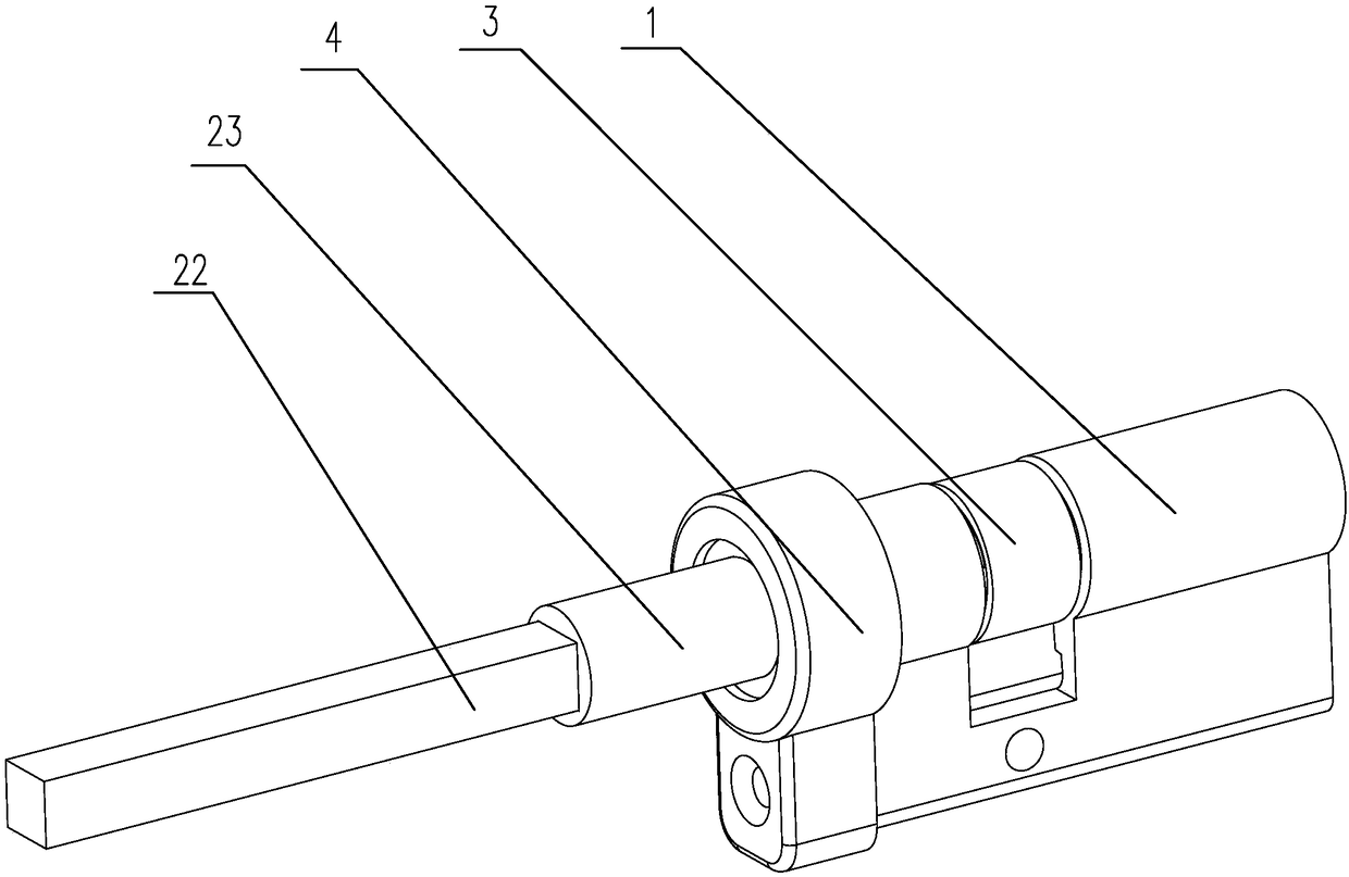
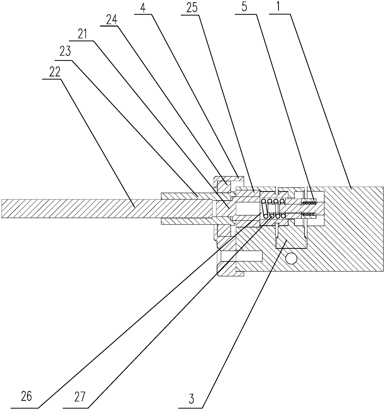
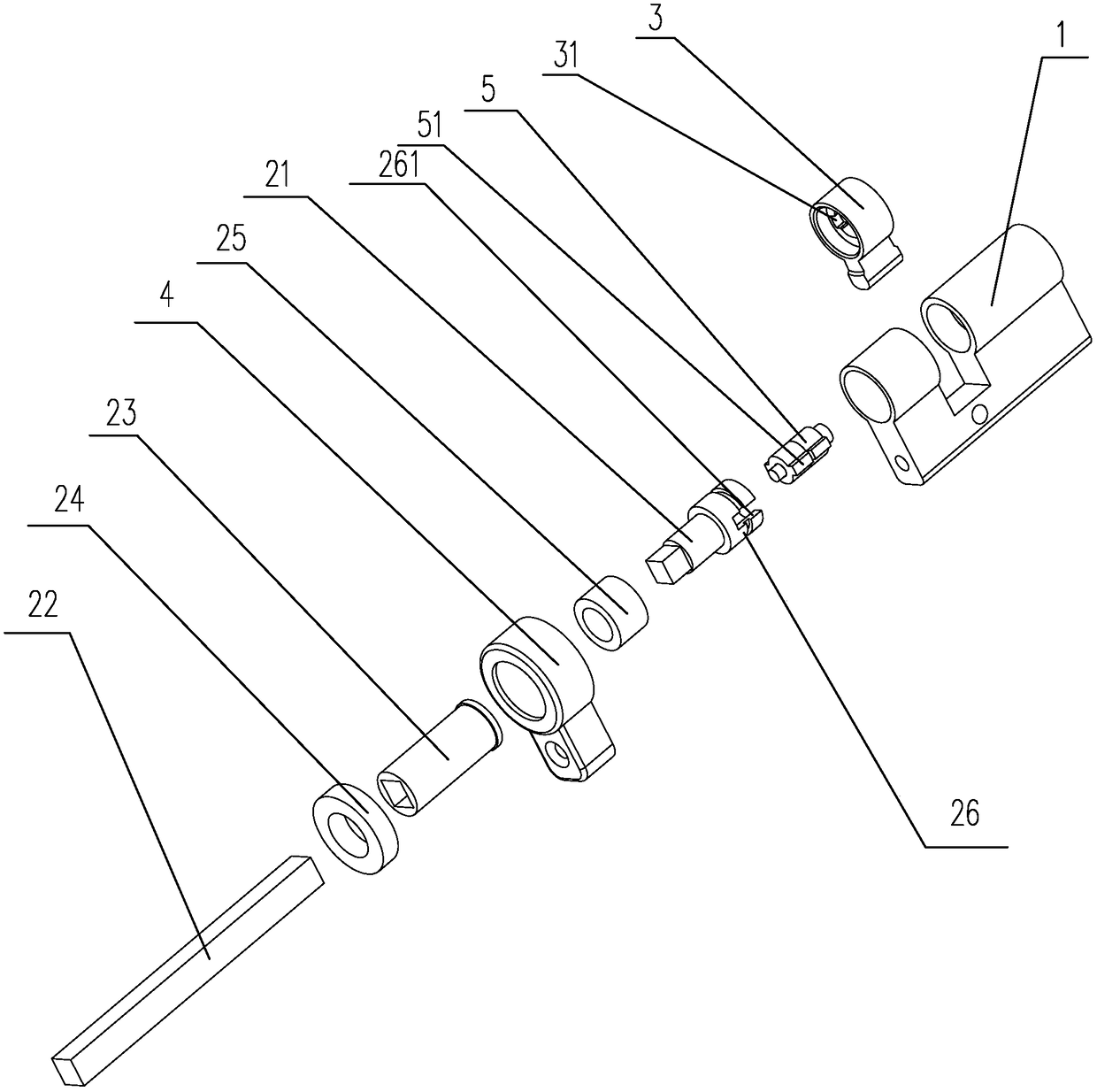
[0013] Depend on Figure 1 to Figure 3 It can be seen that the present invention discloses a tumbler lock, comprising a lock case 1, a square shaft, a lock cylinder and a fixing bracket 4 for fixing the lock case 1 on the door body, and the lock case 1 is clamped on a fixed On the bracket 4, the lock cylinder is arranged in the lock case 1, the square shaft includes a connecting shaft 21 and an extension shaft 22, and the front end of the connecting shaft 21 is formed with a connecting seat 26 and is rotatably inserted in the lock case 1 , the rear end is square and exposed to the outside of the lock case 1, the connecting seat 26 is opened and forms a sliding cavity, the side wall of the connecting seat 26 is provided with a linkage slot 261, the connecting seat 26 and the lock cylinder A sliding block 5 and a dial 3 are arranged therebetween, the dial 3 is linked with the lock cylinder, a limit groove 31 is arranged on the inner wall of the dial 3, and the sliding block 5 is...


PUM


Abstract

The invention discloses a spring lock. The spring lock comprises a lock case, a square shaft, a lock cylinder and a fixing bracket for fixing the lock case to a door body, wherein the lock case is arranged on the fixing bracket; the lock cylinder is arranged in the lock case; the square shaft comprises a connecting shaft and an extending shaft; the front end of the connecting shaft is rotatably inserted into the lock case while the back end of the connecting shaft is square and is exposed out of the lock case; one end of the extending shaft is connected to the back end of the connecting shaftthrough a shaft sleeve while the other end of the extending shaft is a free end which is square; the shaft sleeve is arranged through the fixing bracket; a first bearing is arranged between the shaftsleeve and the fixing bracket; the first bearing is arranged on the shaft sleeve in a sleeving manner; a second bearing is arranged between the connecting shaft and the lock case; the second beraing is arranged on the connecting shaft in a sleeving manner; the connecting shaft is linked to the lock cylinder; and a separating part for separating the lock cylinder and the connecting shaft is arranged between the connecting shaft and the lock cylinder. The spring lock disclosed by the invention is simple and reasonable in structure, avoids a locking phenomenon of the square shaft and the lock case, and is easily combined with a coded lock in use.

Description

technical field [0001] The invention relates to the technical field of locks, in particular to a tumbler lock which operates smoothly and is not easily jammed. Background technique [0002] Pin locks, also known as marble locks, bead locks, deadbolt locks, or pin locks, are the most common lock construction. The principle is to use a plurality of cylindrical parts of different heights, which are called lock springs, marbles or beads, to lock the lock cylinder and limit the rotation of the lock cylinder. When the correct key is put in, each marble is pushed to the same height, and the lock cylinder is released and can be rotated, thereby driving the square shaft to rotate to realize unlocking. However, the existing pin locks are usually used in conjunction with combination locks. Direct unlocking, on the other hand, you can use the motor to drive the square shaft to rotate to unlock by inputting the password. After the square shaft is driven to rotate, the square outer edge ...

Claims


Application Information

Patent Timeline
Patent Type & Authority Applications(China)
IPC IPC(8): E05B27/00E05B37/00
CPCE05B27/00E05B37/0034
Inventor 郑军勇郑富军
Owner 深圳市诺尔巴克科技有限公司
Features
  • R&D
  • Intellectual Property
  • Life Sciences
  • Materials
  • Tech Scout
  • Unparalleled Data Quality
  • Higher Quality Content
  • 60% Fewer Hallucinations
Learn More