Protection device, and electronic device comprising the same

A protective device and accommodating cavity technology, which is applied to televisions, electrical components, color televisions, etc., can solve the problems of poor dustproof and waterproof effects, and achieve the effects of good waterproof effects, simple structure, and convenient processing and production

Active Publication Date: 2018-07-24
SHANGHAI CHUANGGONG COMM TECH
View PDF5 Cites 11 Cited by
  • Summary
  • Abstract
  • Description
  • Claims
  • Application Information

AI Technical Summary

Problems solved by technology

[0004] The technical problem to be solved by the present invention is to provide a protective device and electronic equipment containing it in order to overcome the defects of the prior art such as poor dustproof and waterproof effects

Method used


Image

  • Protection device, and electronic device comprising the same
  • Protection device, and electronic device comprising the same
  • Protection device, and electronic device comprising the same

Examples


Embodiment 1

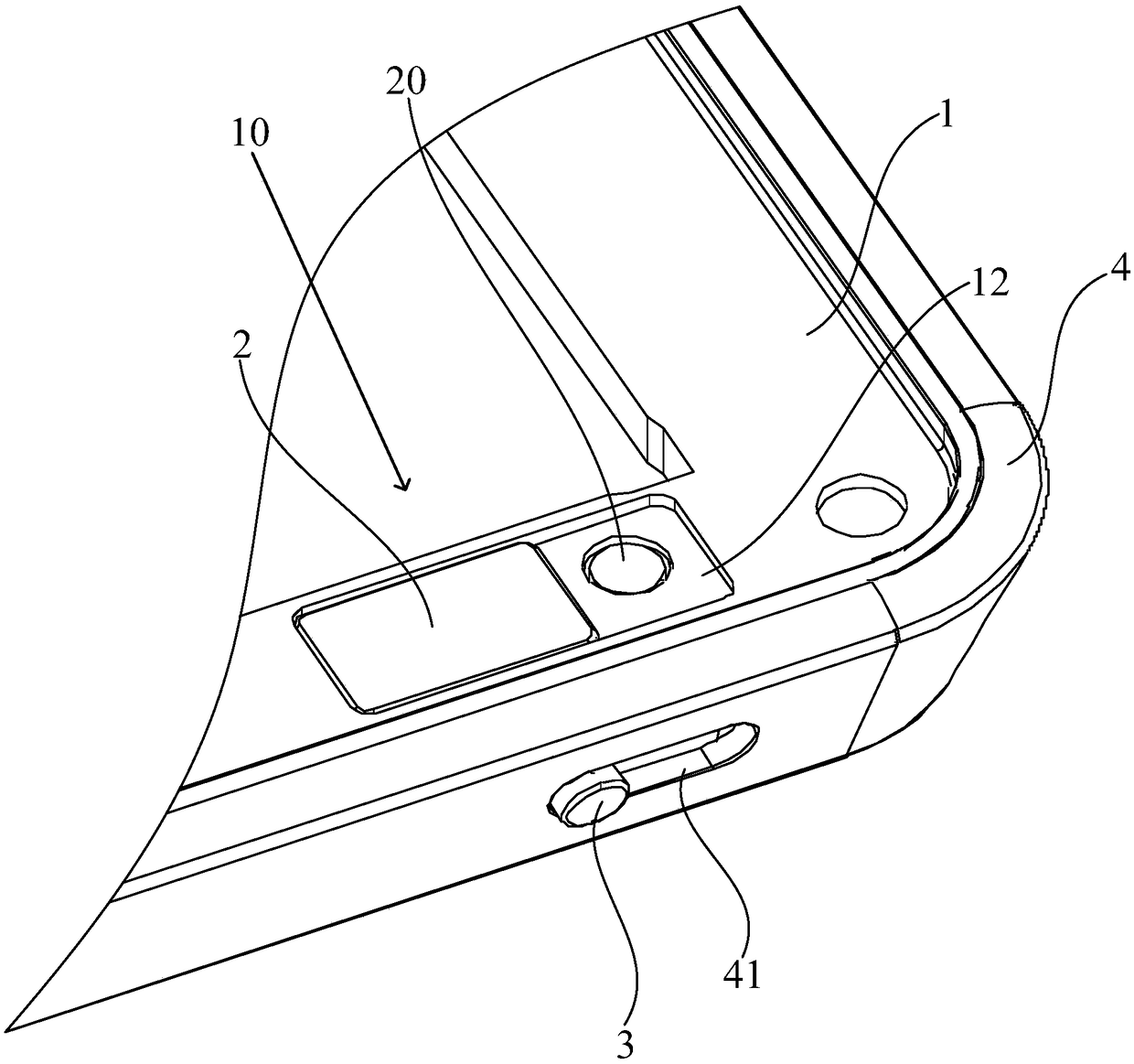
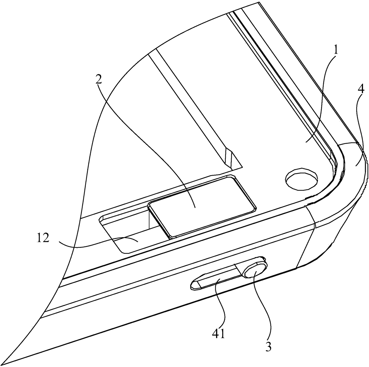
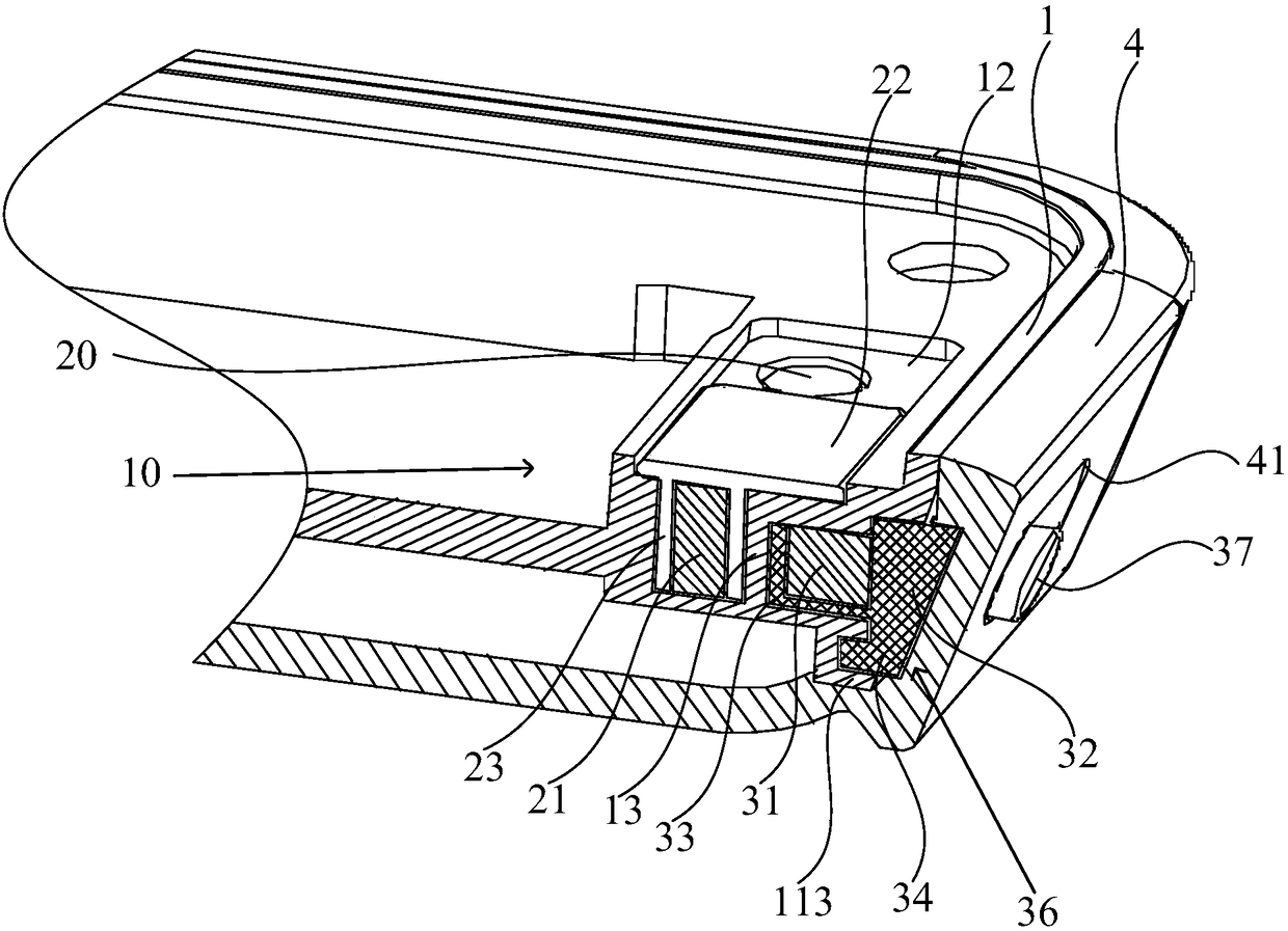
[0087] Such as Figure 1 to Figure 6 As shown, the electronic equipment in the embodiment of the present invention includes a protective device 10 and a camera 20 , and the protective device 10 is used to protect the camera 20 . The protective device 10 includes a first housing 1, a shielding member 2 and a toggle member 3. The camera 20 can be placed in the front or rear of the first housing 1 of the electronic device. The camera 20 in the embodiment of the present invention is placed in the front Inside the first casing 1 of the electronic device. Wherein, in the electronic equipment of the embodiment of the present invention, the first housing 1 in the protection device 10 is also the housing structure of the electronic equipment.

[0088] The shutter 2 is located inside the first housing 1, the dial 3 is located outside the first housing 1 and slides on the first housing 1, and the shutter 2 and the dial 3 pass through the first housing 1 Physical isolation is realized, ...

Embodiment 2

[0111] Such as Figure 7 , Figure 8 with Figure 9 As shown, the structure of the electronic device of this embodiment is the same as that of Embodiment 1 and will not be repeated, only the differences will be described. In the electronic device of this embodiment, the sliding direction of the toggle member 3 is perpendicular to the sliding direction of the shielding member 2 . And in the electronic device of this embodiment, the magnetic properties of the first magnet 31 and the second magnet 21 are different.

[0112] At the initial position, the shutter 2 is farthest from the toggle 3 , and the camera 20 is disposed between the shutter 2 and the toggle 3 , and the shutter 2 exposes the camera 20 at this time. When the toggle member 3 slides on the first housing 1 and the distance between the first magnet 31 and the second magnet 21 is the shortest, the magnetic force between the first magnet 31 and the second magnet 21 is the largest, because the magnetic force As a re...


PUM


Abstract

The invention discloses a protection device, and an electronic device comprising the same. The protection device is used for protecting a camera, the protection device comprises a first housing and ashielding member, the camera is arranged in the first housing, the shielding member is located in the first housing, the protection device further comprises a dialing member, the dialing member is located at the outside the first housing and slides on the first housing, and the shielding member and the dialing member are physically isolated through the first housing; and through the magnetic forcebetween the dialing member and the shielding member, the shielding member slides in the first housing and is used for exposing or shielding the camera. The electronic device comprises a camera and the protection device. According to the protection device, the shielding of the camera is implemented by driving the shielding member to slide through the magnetic force of a second magnet and a first magnet, the structural form is simple, the space occupation is small, the use is convenient, the dustproof and waterproof effects are good, and the service life is long.

Description

technical field [0001] The invention relates to a protective device and electronic equipment containing it. Background technique [0002] With the rapid development of intelligent electronic equipment technology, the use of electronic equipment is becoming more and more popular. At the same time, modern society attaches great importance to the information security of personal images (pictures and videos), and the requirements for information security of end users are getting higher and higher. [0003] At present, the mainstream security method on the market is to set a baffle on the housing of the electronic device, and use the baffle to block the camera to avoid privacy being leaked by sneak shots. For example, a wall camera with a mechanical locking device disclosed in Chinese patent ZL201620746273.5 has a through hole on the cover plate, which is exposed to the outside through the through hole, so as to be used to push the baffle, which is realized by the movement of th...

Claims


Application Information

Patent Timeline
Patent Type & Authority Applications(China)
IPC IPC(8): H04N5/225G03B17/56G03B17/02G03B30/00
CPCG03B17/56H04N23/50H04N23/57H04N23/51
Inventor 孙玉培姜洋
Owner SHANGHAI CHUANGGONG COMM TECH
Why Eureka
Try Eureka