Dedusting device for spinning

A technology of dust removal device and filter device, which is applied in the direction of combined device, electrostatic effect separation, and dispersed particle filtration, etc., which can solve the problems of dust removal device clogging, large volume, and affecting the health of operators

Inactive Publication Date: 2018-07-27
HAINING MEILI KNITTING CO LTD
View PDF2 Cites 0 Cited by
  • Summary
  • Abstract
  • Description
  • Claims
  • Application Information

AI Technical Summary

Problems solved by technology

In the process of weaving, such as: cotton opening, cotton blending, etc., a lot of dust and fiber filaments will be produced. If you inhale cotton, hemp and other dust for a long time, it will cause great harm to the human body, and may cause airway obstruction diseases. There are chest tightness, chest tightness, and shortness of breath. Therefore, it is necessary to install a dust removal device in the working environment to remove the sundries in the environment. However, most of the dust removal machines currently on the market are large in size and high in price. Production costs, so no dust removal machine is installed, but this is very detrimental to the safety of operators in the workshop
[0003] There are a large number of textile machines in the textile workshop. When the textile machines are working, a large amount of redundant cloth scraps and strips will be generated, which will cause serious pollution to the air quality and affect the health of the operators. Measures must be taken for dust removal.
There is a dust removal device, which uses a fan to suck cloth dust into the dust storage bag of the fan, but some of the cloth dust is relatively large, which is easy to block the dust removal device and cannot work normally. Dirty air affects people's mood , leading to low work efficiency

Method used


Image

  • Dedusting device for spinning
  • Dedusting device for spinning
  • Dedusting device for spinning

Examples


Embodiment Construction

[0023] The following will clearly and completely describe the technical solutions in the embodiments of the present invention with reference to the accompanying drawings in the embodiments of the present invention. Obviously, the described embodiments are only some, not all, embodiments of the present invention.

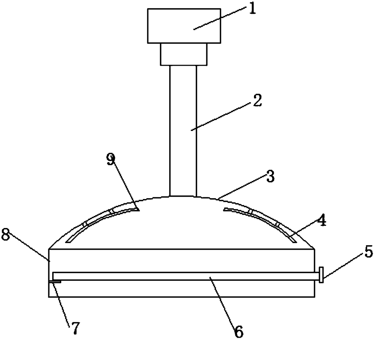
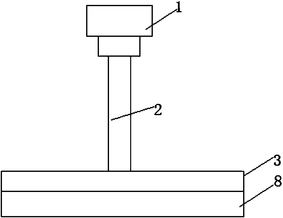
[0024] refer to Figure 1-4 , a textile dust removal device, including a housing 8, a fixed buckle 7 is welded on the side wall of the inner cavity of the housing 8, and a rectangular hole is opened on the side wall opposite to the fixed buckle 7 on the housing 8 , the upper part of the housing 8 is welded with a top cover 3, the inner cavity of the top cover 3 communicates with the inner cavity of the housing 8, the top of the housing 8 is welded with a ventilation pipe 2, and the end of the ventilation pipe 2 away from the housing 8 is connected to the exhaust fan. The air inlet end of 1 is connected by a flange, the top of the inner cavity of the top cover 3 is fi...


PUM


Abstract

The invention discloses a dedusting device for spinning; the dedusting device includes a shell. A fixing buckle is welded on the side wall of an inner cavity of the shell, and a rectangular hole is formed in a part, opposite to the fixing buckle, on the shell, and the upper part of the shell is welded with a top cover; an inner cavity of the top cover communicates with the inner cavity of the shell, and a ventilating tube is welded on the top of the shell; one end, away from the shell, of the ventilating tube is connected with a wind inlet end of an exhaust fan through a flange plate; the topof the inner cavity of the top cover is fixed with a first electrode rod and a second electrode rod through a bracket; a filter device is placed in the inner cavity of the shell and includes a fixed frame and a filter layer, and one end, located outside the shell, of the filter device is welded with a limit plate. The dedusting device for spinning is provided with a driving mechanism and also is provided with a primary filter mechanism and a secondary filter device; with cooperative use of the primary filter mechanism and the secondary filter device, dust can be fully filtered, so that the worker body health is facilitated; the dedusting device is simple in structure, low in cost, easy to produce and easy to maintain.

Description

technical field [0001] The invention relates to the technical field of textile auxiliary equipment, in particular to a textile dust removal device. Background technique [0002] With the substantial improvement of people's living standards, people's requirements for quality of life are getting higher and higher, so the demand for textiles is also increasing. The raw materials of the textile industry mainly include: natural fibers (cotton, wool, silk, hemp), man-made fibers and synthetic fibers. In the process of weaving, such as: cotton opening, cotton blending, etc., a lot of dust and fiber filaments will be produced. If you inhale cotton, hemp and other dust for a long time, it will cause great harm to the human body and may cause airway obstruction diseases. There are chest tightness, chest tightness, and shortness of breath. Therefore, it is necessary to install a dust removal device in the working environment to remove the sundries in the environment. However, most of ...

Claims


Application Information

Patent Timeline
Patent Type & Authority Applications(China)
IPC IPC(8): B01D46/12B01D50/00B03C3/017
CPCB01D46/12B01D50/00B03C3/017
Inventor 不公告发明人
Owner HAINING MEILI KNITTING CO LTD
Why Eureka
Try Eureka