Efficient filtration and separation treatment equipment for textile wastewater

A textile wastewater and high-efficiency filtration technology, which is applied in the direction of textile industrial wastewater treatment, filtration treatment, centrifugal separation water/sewage treatment, etc., can solve the problems that the filtering effect needs to be improved, the filter net is easy to be blocked, and the replacement is inconvenient.

Pending Publication Date: 2022-06-07
浙江合泽资源循环有限公司
View PDF0 Cites 0 Cited by
  • Summary
  • Abstract
  • Description
  • Claims
  • Application Information

AI Technical Summary

Problems solved by technology

Some existing textile wastewater treatment equipment first need to filter and separate the solid waste and floc in the textile wastewater, but the inventors found that after the above equipment is used, the filter screen is easy to block, and it is inconvenient to replace, and the solid waste and floc Therefore, aiming at the above problems, the present invention designs a high-efficiency filtration and separation treatment equipment for textile wastewater.

Method used


Image

  • Efficient filtration and separation treatment equipment for textile wastewater
  • Efficient filtration and separation treatment equipment for textile wastewater
  • Efficient filtration and separation treatment equipment for textile wastewater

Examples


Embodiment 1

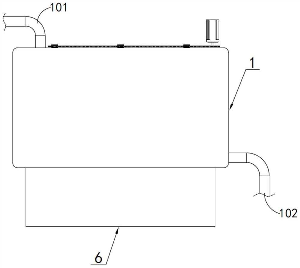
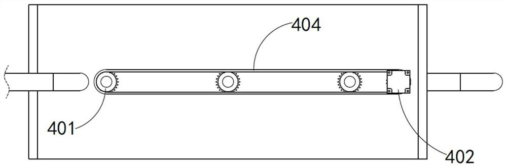
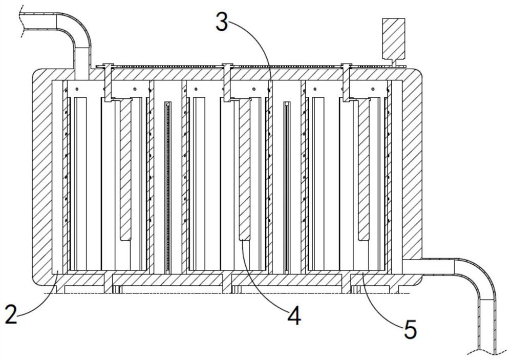
[0031] like Figure 1 to Figure 9 As shown, the embodiment of the present invention provides a high-efficiency filtration and separation treatment equipment for textile waste water, including a filter box 1, a plurality of filter cavities 2 are arranged inside the filter box 1, and a separation cylinder 3 and a filter cavity 2 are arranged in the filter cavity 2. The rotating stirring blade 4 is matched with the separation drum 3. The separation drum 3 is used to accommodate the textile waste water and agitate and rotate the textile waste water by rotating the stirring blade 4, so that the impurities in the textile waste water are gathered in the center of the vortex. A number of discharge water holes 301 and a jacking control ring 5 are respectively provided, and the jacking control ring 5 keeps the liquid level of the textile waste water in the separation cylinder 3 always at the same height as the uppermost water outlet hole 301 in the vertical direction by jacking up. Duri...

Embodiment 2

[0043] as attached Figure 4 As shown in the figure, the same or corresponding parts as in the first embodiment are marked with the corresponding reference numerals as in the first embodiment. For the sake of brevity, only the differences from the first embodiment are described below; the difference between the second embodiment and the first embodiment The difference lies in that a filter screen 201 is also arranged between the filter chambers 2, and the filter screen 201 is used for the secondary filtering of the separated textile waste water discharged between the separation cylinders 3, and the rear side of the filter box 1 corresponds to each filter chamber 2 is also provided with a cleaning door, and opening the cleaning door can clean the solid waste remaining in the separation cylinder 3 after filtration and separation.

[0044] The working principle of the present invention is as follows:

[0045] The textile waste water enters the separation cylinder 3 through the c...


PUM


Abstract

The invention relates to textile wastewater efficient filtering and separating treatment equipment which comprises a filtering box body, a plurality of filtering cavities are formed in the filtering box body, and separating cylinders and rotating stirring blades matched with the separating cylinders are arranged in the filtering cavities; the separation barrel is used for containing textile wastewater and stirring and rotating the textile wastewater through the rotating stirring blades to enable impurities in the textile wastewater to be gathered towards the center of a vortex, and the outer wall and the interior of the separation barrel are further provided with a plurality of rows of water discharging holes and a jacking control ring correspondingly; the jacking control ring enables the liquid level of the textile wastewater in the separation cylinder to be always kept at the same height as the uppermost water outlet hole in the vertical direction in a jacking manner; the jacking control ring also controls the water outlet hole to be communicated with the textile wastewater in a self-rotation manner in the jacking process, so that the textile wastewater separated from the outer side of the vortex is discharged outwards through the water outlet hole, and primary filtration of solid wastes and floccules in the textile wastewater is realized in a rotary separation manner.

Description

technical field [0001] The invention relates to the technical field of textile wastewater treatment, in particular to a high-efficiency filtration and separation treatment equipment for textile wastewater. Background technique [0002] With the rapid development of society, the textile printing and dyeing industry has also made rapid progress. The wastewater produced by the textile printing and dyeing industry generally contains a large amount of solid wastes and flocs, such as some dissolved solids and suspended solids. Some existing textile wastewater treatment equipment first needs to filter and separate the solid waste and floc in the textile wastewater, but the inventor found that after the above equipment is used, the filter screen is easy to be blocked, and it is inconvenient to replace, and the solid waste and floc are not easy to be replaced. Therefore, in view of the above problems, the present invention designs a high-efficiency filtration and separation treatmen...

Claims


Application Information

Patent Timeline
Patent Type & Authority Applications(China)
IPC IPC(8): C02F9/02C02F103/30
CPCC02F1/38C02F1/001C02F2103/30Y02W10/10
Inventor 钱洲叶士杰
Owner 浙江合泽资源循环有限公司
Why Eureka
Try Eureka