Eureka AIR delivers breakthrough ideas for toughest innovation challenges, trusted by R&D personnel around the world.

Silicon wafer cutting machine with cutting fluid recycling function

A cutting fluid and cutting machine technology, which is applied to fine working devices, stone processing equipment, manufacturing tools, etc., can solve the problems of wasting cutting fluid, ineffective recycling of cutting fluid, and lack of cutting fluid recovery devices. The effect of improving filtration efficiency

Inactive Publication Date: 2021-12-07
江苏天晶智能装备有限公司
View PDF0 Cites 0 Cited by
  • Summary
  • Abstract
  • Description
  • Claims
  • Application Information

AI Technical Summary

Problems solved by technology

[0002] my country's photovoltaic solar technology is at a mature stage. In order to develop pollution-free energy, a large number of silicon wafers are used in the production process of photovoltaic solar energy, and silicon wafers need to be cut into sheets by a silicon wafer cutting machine. The existing silicon wafer cutting machine equipment In terms of equipment, there is a lack of cutting fluid recovery devices, and in the cutting process, silicon wafer cutting fluid is used as an auxiliary material consumable product that must be used in the silicon wafer cutting process, and the cutting fluid cannot be effectively recycled and reused every year, resulting in a large amount of cutting waste liquid

Method used


Image

  • Silicon wafer cutting machine with cutting fluid recycling function
  • Silicon wafer cutting machine with cutting fluid recycling function
  • Silicon wafer cutting machine with cutting fluid recycling function

Examples


Embodiment 1

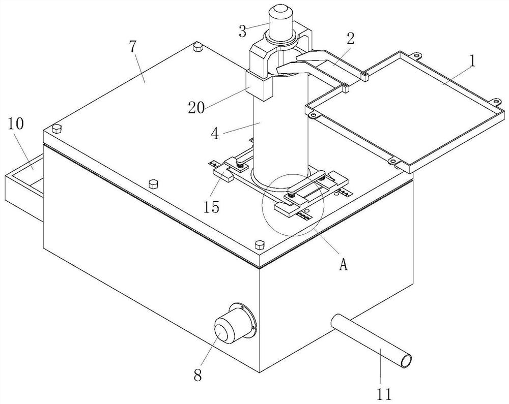
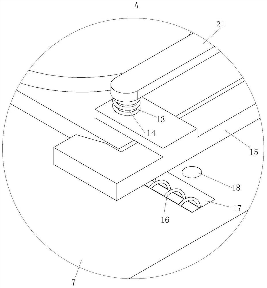
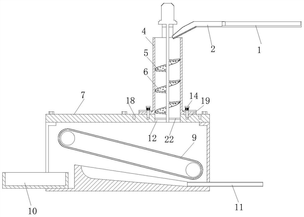
[0023] refer to Figure 1-3 , a silicon wafer cutting machine with cutting fluid recovery function, comprising a deflector 1 for collecting cutting fluid, a diversion groove 2 is provided on one side of the deflector 1, and the outlet end of the diversion groove 2 is provided with a The primary filter mechanism for cutting fluid recovery, the primary filter mechanism is used to filter out particulate debris in the cutting fluid, and a secondary filter mechanism for cutting fluid recovery is provided below the primary filter mechanism, and the secondary filter mechanism is used to filter out the cutting fluid. The powdery debris and the primary filter mechanism and the secondary filter mechanism are connected by a quick release mechanism.

[0024] The primary filter mechanism includes a No. 1 motor 3, a tower cylinder 4 and a spiral blade 5; the lower end of the tower cylinder 4 is connected to the secondary filter mechanism connected to the tower cylinder 4 through a quick rel...

Embodiment 2

[0032] refer to Figure 4 , Comparative Example 1, as another embodiment of the present invention, wherein the edge of the guide plate 1 is provided with connecting ears 23, the guide plate 1 is fixed under the silicon wafer cutting machine through the connecting ears 23, 23. It is convenient to fix the deflector 1 .

[0033] Working principle: The cutting fluid flows into the tower 4 from the deflector 1 and the diversion groove 2, and the No. 1 motor 3 is rotated by the electric spiral blade 5. During the rotation, the cutting fluid is stirred and filtered. One is to improve the filtration efficiency. The second is to prevent debris from blocking the overflow hole 6. The debris in the cutting fluid that can pass through the overflow hole 6 directly falls into the box 7, and the debris that fails to pass through the overflow hole 6 is filtered in the spiral blade. 5. At this time, the primary filtration of the cutting fluid is realized, that is, the large particles of debris...


PUM


Abstract

The invention relates to the field of cutting machines, in particular to a silicon wafer cutting machine with a cutting fluid recycling function. The silicon wafer cutting machine comprises a flow guide plate for collecting cutting fluid, a flow guide groove is formed in one side of the flow guide plate, a primary filtering mechanism for recycling the cutting fluid is arranged at the outlet end of the flow guide groove, the primary filtering mechanism is used for filtering granular impurities in the cutting fluid, a secondary filtering mechanism for recycling the cutting fluid is arranged below the primary filtering mechanism, the secondary filtering mechanism is used for filtering powdery impurities of the cutting fluid, and the primary filtering mechanism and the secondary filtering mechanism are connected through a quick release mechanism. The cutting fluid flows into a tower barrel from the flow guide plate and the flow guide groove, debris, capable of passing through overflow holes, in the cutting fluid directly falls into a box body, debris which cannot pass through the overflow holes is filtered on spiral blades, and at the moment, primary filtering of the cutting fluid is achieved, namely large-particle debris in the cutting fluid is filtered out.

Description

technical field [0001] The invention relates to the field of cutting machines, in particular to a silicon wafer cutting machine with a cutting fluid recovery function. Background technique [0002] my country's photovoltaic solar technology is in a mature stage. In order to develop pollution-free energy, a large number of silicon wafers are used in the production process of photovoltaic solar energy, and the silicon wafers need to be cut into sheets by a silicon wafer cutting machine. On the other hand, there is a lack of a cutting fluid recovery device, and in the cutting process, silicon wafer cutting fluid is a kind of auxiliary consumable product that must be used in the silicon wafer cutting process, and the cutting fluid cannot be effectively recycled every year, resulting in a large amount of cutting waste. liquid. SUMMARY OF THE INVENTION [0003] In order to make up for the prior art, the present invention proposes a silicon wafer cutting machine with a cutting flu...

Claims


Application Information

Patent Timeline
IPC IPC(8): B28D5/00
CPCB28D5/007
Inventor 张耀黄慧媛齐申屈恒
Owner 江苏天晶智能装备有限公司
Why Eureka
Eureka Blog
Learn More