Two-axis and three-axis pan-tilts and shooting equipment thereof

A technology of two-axis gimbal and pin shaft, which can be used in mechanical equipment, machine/bracket, optics, etc., and can solve problems such as large size of gimbal.

Active Publication Date: 2018-07-27
北京远度互联科技有限公司
View PDF5 Cites 8 Cited by
  • Summary
  • Abstract
  • Description
  • Claims
  • Application Information

AI Technical Summary

Problems solved by technology

[0004] The present invention aims to provide a two-axis cloud platform to

Method used


Image

  • Two-axis and three-axis pan-tilts and shooting equipment thereof
  • Two-axis and three-axis pan-tilts and shooting equipment thereof
  • Two-axis and three-axis pan-tilts and shooting equipment thereof

Examples


Example Embodiment

[0036] Example 1

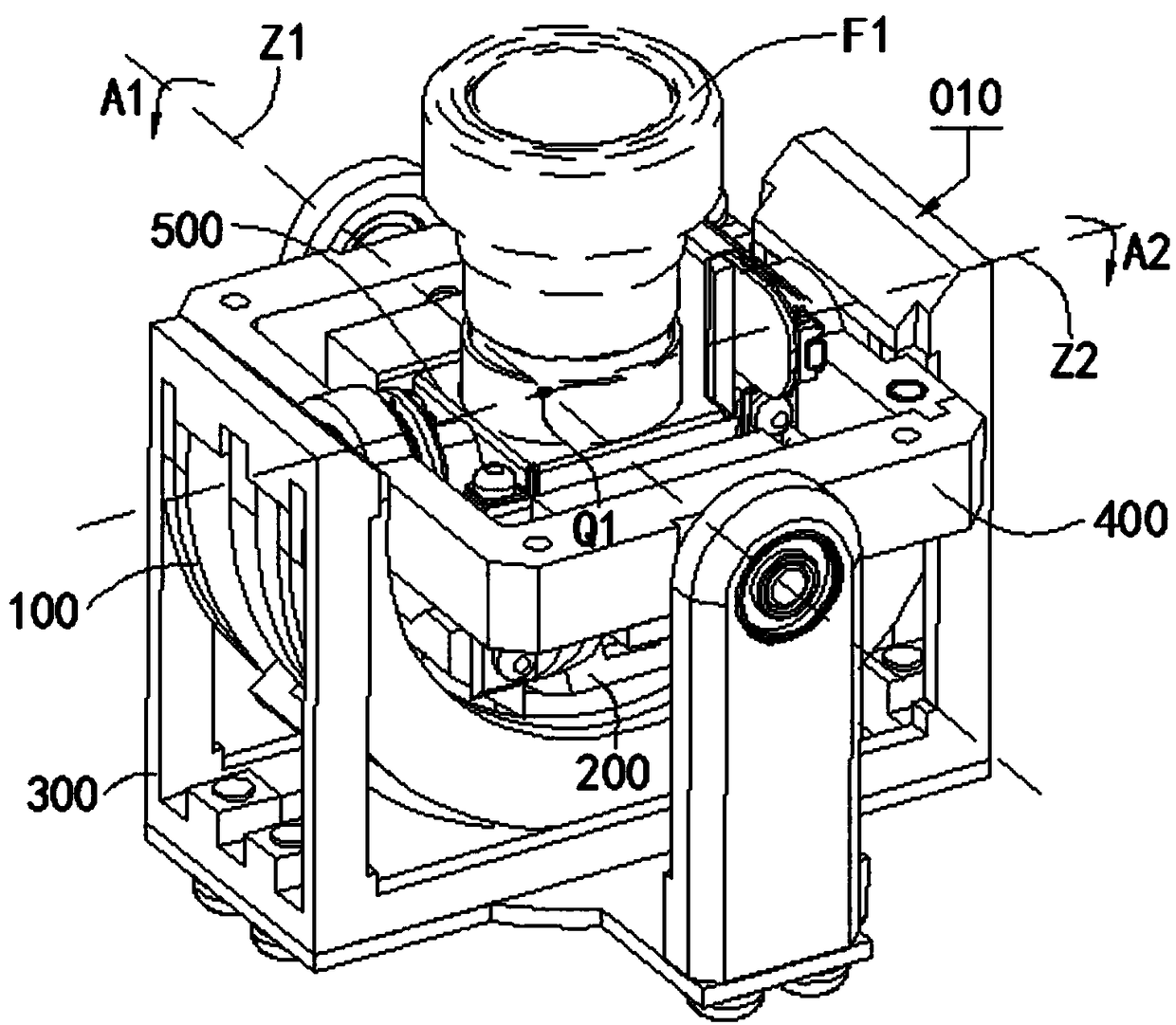
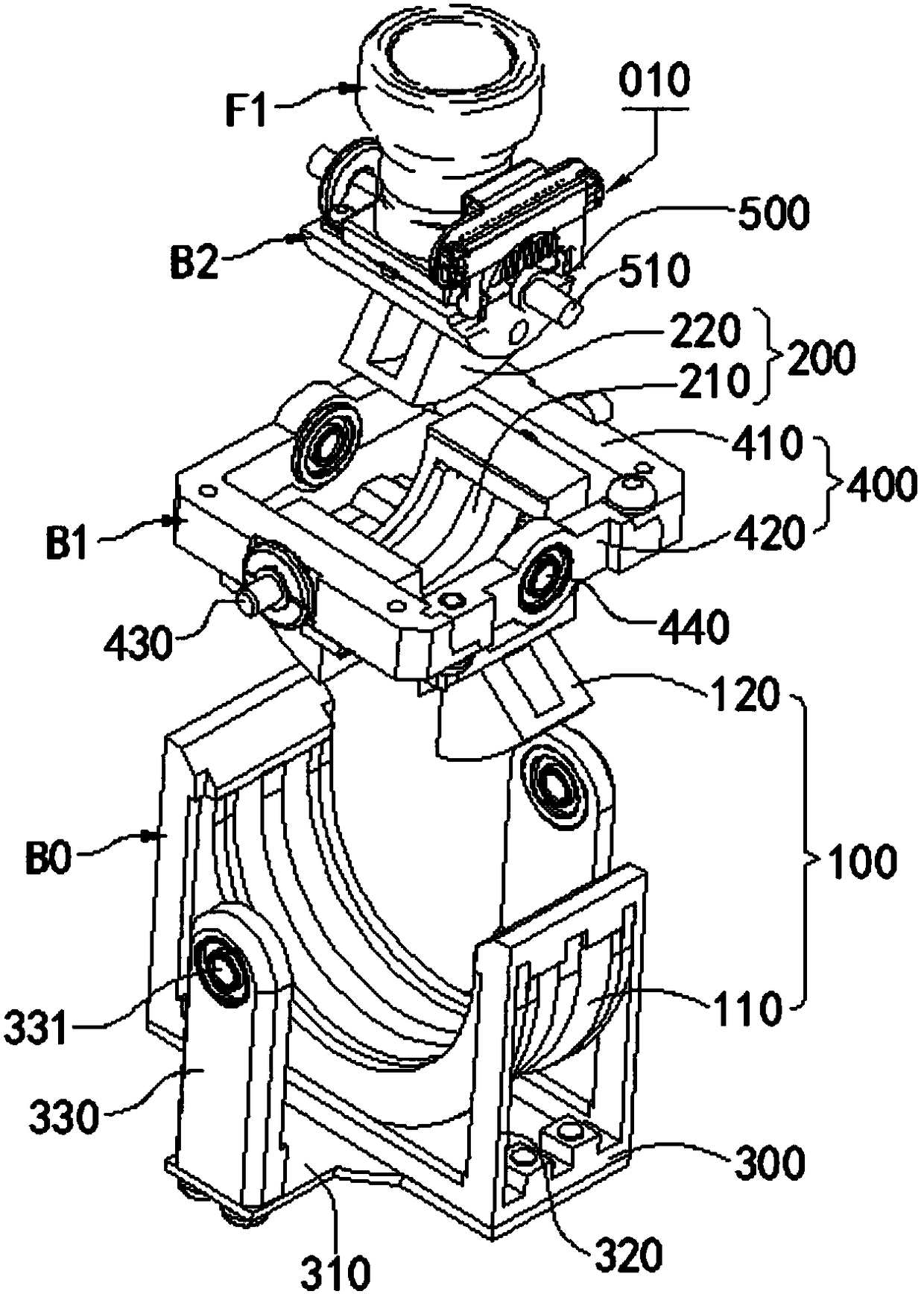
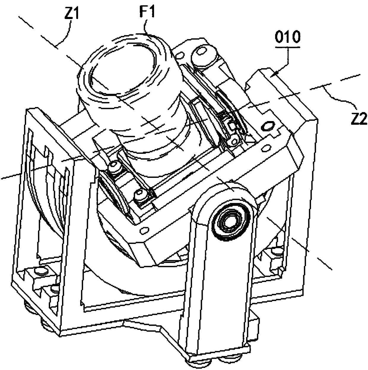
[0037] figure 1 It is a schematic structural diagram of the two-axis gimbal 010 in the first embodiment of the present invention. figure 2 Yes figure 1 exploded view. In order to show its use status, figure 1 , figure 2 The dotted line in the middle additionally shows the structure of the load device F1 to which the two-axis pan / tilt head 010 in this embodiment is used is connected.

[0038] See figure 1 , the two-axis pan / tilt 010 in this embodiment includes a first motor 100 and a second motor 200, a base 300 and a rotating base 400 for supporting or connecting the first motor 100 and the second motor 200, and a load device for installing Load connector 500 for F1. The first motor 100 and the second motor 200 are both swing angle voice coil motors.

[0039] See figure 2 (see also figure 1 ), the first motor 100 includes a first stator 110 and a first mover 120 that cooperate with each other. The second motor 200 includes a second stator 210 a...

Example Embodiment

[0055] Embodiment 2

[0056] Figure 7 It is a schematic structural diagram of the three-axis pan / tilt 020 in the second embodiment of the present invention. In order to show its use status, Figure 7 The dotted line in the middle additionally shows the structure of the load device F1 to which the three-axis pan / tilt head 020 in this embodiment is used is connected.

[0057] See Figure 7 , the three-axis gimbal 020 in this embodiment includes a third motor 600 and the two-axis gimbal 010 in the first embodiment. The third motor 600 is a rotary motor composed of a fixed part 610 and a rotating part 620 that are rotatably matched. The rotating part 620 of the third motor 600 is relatively fixedly connected to the first stator 110 . Preferably, the rotation axes of the first rotation axis Z1 , the second rotation axis Z2 and the third motor 600 are perpendicular to each other and intersect at one point. Hereinafter, the rotation axis of the third motor 600 is named as the ...

Example Embodiment

[0059] Embodiment 3

[0060] Figure 8 It is a schematic structural diagram of the three-axis pan / tilt 030 in the third embodiment of the present invention. In order to show its use status, Figure 8 The dotted line in the middle additionally shows the structure of the load device F1 to which the three-axis pan / tilt head 030 in this embodiment is used is connected.

[0061] The three-axis gimbal 030 in this embodiment includes a third motor 600 and the two-axis gimbal 010 in the first embodiment.

[0062] The third motor 600 is a rotary motor composed of a fixed part 610 and a rotating part 620 that are rotatably matched. The fixing part 610 of the third motor 600 is fixedly connected to the second mover 220 , and the rotating part 620 of the third motor 600 is used for connecting to the load device F1 . Preferably, the rotation axes of the first rotation axis Z1 , the second rotation axis Z2 and the third motor 600 are perpendicular to each other and intersect at one poin...


PUM


Abstract

The invention relates to pan-tilt structures and the application field thereof and provides a two-axis pan-tilt in order to solve the problem that a pan-tilt in the prior art is large in size. The two-axis pan-tilt is used for driving a load device and comprises a first motor and a second motor, the first motor and the second motor are swing angle voice coil motors correspondingly, and the first motor comprises a first stator and a first rotor which are matched with each other. The second motor comprises a second stator and a second rotor which are matched with each other, the first rotor is connected with the second stator in a matched mode and used for driving the second motor to move, and the rotation axis of the first motor is not parallel with the rotation axis of the second motor. The load device is connected to the second rotor. The invention further provides a three-axis pan-tilt with the two-axis pan-tilt, two-axis shooting equipment and three-axis shooting equipment. The two-axis and three-axis pan-tilts and the shooting equipment thereof have the beneficial effects that the structure is compact, space planning is reasonable, and the size is small.

Description

technical field [0001] The invention relates to a platform structure and its application field. Specifically, it relates to a two-axis gimbal. The invention also relates to a two-axis shooting device based on the two-axis platform. The present invention also relates to a three-axis pan-tilt based on the aforementioned two-axis pan-tilt, and a three-axis shooting device based on the three-axis pan-tilt. Background technique [0002] The pan / tilt is a supporting workbench for installing a load device, and is usually used for installing imaging devices such as video cameras and cameras. When the imaging device is fixed on the pan-tilt, its position and angle can be changed by driving the imaging device to move through the pan-tilt, so as to realize active tracking and positioning of the object to be photographed. The movement of the imaging device driven by the pan / tilt can also be used to compensate the influence of environmental disturbances (such as bad vibration) on the ...

Claims


Application Information

Patent Timeline
IPC IPC(8): F16M11/12F16M11/18F16M13/02F16M13/04G03B17/56B64D47/08G03B30/00
CPCG03B17/561F16M11/121F16M11/18F16M13/02F16M13/04B64D47/08
Inventor 付欣谢张涛杨建军
Owner 北京远度互联科技有限公司
Why Eureka
Try Eureka