[0032] Hereinafter, the present invention will be described in detail with reference to the accompanying drawings.
[0033] In the description of the present invention, it should be understood that the terms "longitudinal", "lateral", "upper", "lower", "front", "rear", "left", "right", "vertical", The orientation or positional relationship indicated by "horizontal", "top", "bottom", "inner", "outer", etc. is based on the orientation or positional relationship shown in the drawings, and is only for the convenience of describing the present invention and simplifying the description. It does not indicate or imply that the pointed device or element must have a specific orientation, be constructed and operated in a specific orientation, and therefore cannot be understood as a limitation of the present invention.
[0034] In the description of this specification, descriptions with reference to the terms "one embodiment", "some embodiments", "examples", "specific examples", or "some examples" etc. mean specific features described in conjunction with the embodiment or example , Structure, materials or features are included in at least one embodiment or example of the present invention. In this specification, the schematic representations of the above terms do not necessarily refer to the same embodiment or example. Moreover, the described specific features, structures, materials or characteristics may be combined in any one or more embodiments or examples in a suitable manner.
[0035] In the description of the present invention, unless otherwise specified and limited, it should be noted that the terms "installed", "connected", and "connected" should be understood in a broad sense. For example, they can be mechanically connected or electrically connected, or two The internal communication of the elements may be directly connected or indirectly connected through an intermediate medium. For those of ordinary skill in the art, the specific meaning of the above terms can be understood according to specific conditions.
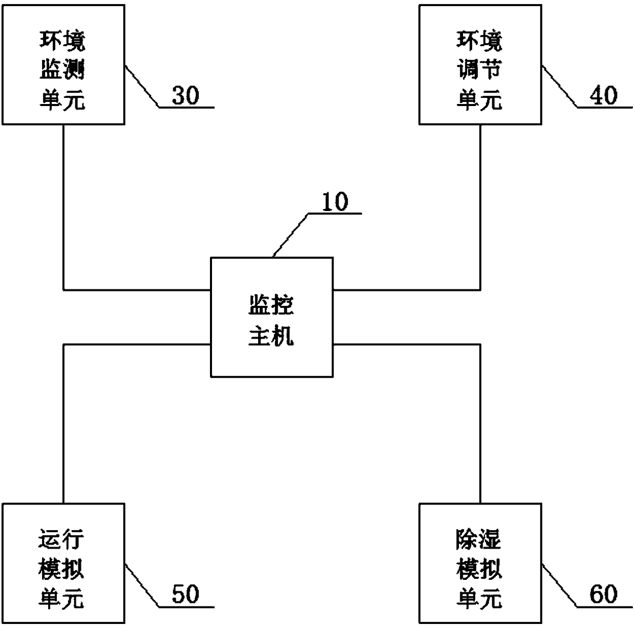
[0036] See figure 1 , The present invention provides a system for studying the mechanism of moisture condensation of a switch cabinet, including: a monitoring host 10, a switch cabinet 20, an environmental monitoring unit 30, an environmental adjustment unit 40, an operation simulation unit 50, and a dehumidification simulation unit 60, wherein the monitoring The host computer 10 is respectively communicatively connected with the environment monitoring unit 30, the environment adjustment unit 40, the operation simulation unit 50, and the dehumidification simulation unit 60;
[0037] The monitoring host 10 can obtain data from the environmental monitoring unit 30, the environmental adjustment unit 40, the operation simulation unit 50, and the dehumidification simulation unit 60 and control the operation of the above units;
[0038] The environmental monitoring unit 30 can measure the environmental parameters inside the switch cabinet 20;
[0039] The environmental adjustment unit 40 can adjust the environmental conditions of the power distribution room 70 where the switch cabinet 20 is located;
[0040] The operation simulation unit 50 can control the operation current of the switch cabinet 20;
[0041] The dehumidification simulation unit 60 can dehumidify the internal environment of the switch cabinet 20.
[0042] Specifically, the monitoring host 10 includes an industrial computer with monitoring analysis software installed in the industrial computer, a communication interface is provided on the industrial computer, and the monitoring host 10 communicates with the environmental monitoring unit 30 and the environmental adjustment unit 40 through the communication interface. , The operation simulation unit 50 and the dehumidification simulation unit 60 are in communication connection.
[0043] The monitoring host 10 can realize the data collection of each unit and the control of the working mode of each unit. By simulating the internal and external working environment and operating conditions of the switch cabinet 20 and the working status of the dehumidification device, the acquired data can be processed and analyzed. Realize the research on the moisture condensation mechanism of switchgear based on test analysis method.
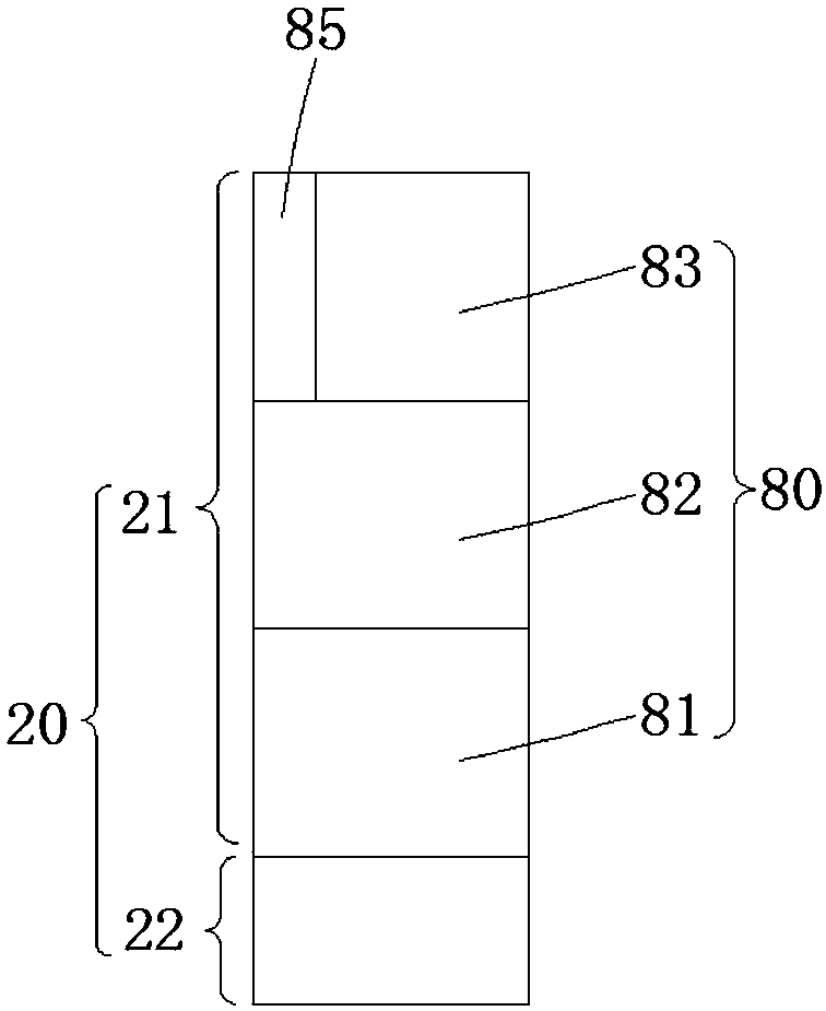
[0044] See figure 2 , The switch cabinet 20 includes a cabinet body 21 in which several compartments 80 are provided. The several compartments 80 include a cable compartment 81, a switch compartment 82, and a busbar compartment 83. Each compartment 80 is All are provided with high-voltage lines and/or high-voltage components, and the voltage on the high-voltage lines and/or high-voltage components is greater than 10kV when the switch cabinet 20 is in operation. The switch cabinet 20 is manufactured according to the standards of the power grid company, and has a standardized cabinet structure and airtightness.
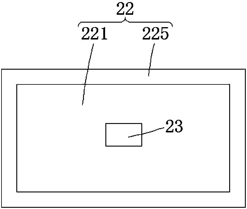
[0045] Further, an insulating member is also installed in the compartment 80. Specifically, the switch cabinet 20 further includes a base 22 arranged below the cabinet 21, the cabinet 21 is mounted on the base 22, the base 22 has a hollow structure, and the base 22 is provided with a water-absorbing sponge. 23. In order to simulate the humidity environment in the cable trench, it is used to study the influence of the humidity in the cable trench on the environment in the switchgear 20.
[0046] See image 3 The base 22 includes a bottom plate 221 and a side plate 225 connected to the bottom plate 221, the side plate 225 is in the shape of a circle, and the bottom plate 221 and the side plate 225 jointly enclose a U-shaped groove for simulating the shape of a cable trench; The water absorbing sponge 23 is arranged in the area enclosed by the side plate 225 on the bottom plate 221; the cabinet body 21 is fixedly installed on the side plate 225.
[0047] Specifically, the cable chamber 81, the switch chamber 82, and the busbar chamber 83 are stacked on the base 22 in order from bottom to top.
[0048] Specifically, the switch cabinet 20 is also provided with an instrument room 85, and low-voltage instruments and low-voltage lines are installed in the instrument room 85. The voltage on the low-voltage instrument and the low-voltage line is less than 1000V, relative to the compartment 80. In terms of internal high-voltage lines and/or high-voltage components, the low-voltage meters and low-voltage lines are not prone to discharge problems due to the influence of moisture. Therefore, the present invention does not study the moisture situation of the meter room 85. Specifically, the meter room 85 and the busbar room 83 are located on the same floor and adjacent to each other.
[0049] Further, the outer shapes of the cabinet body 21 and the base 22 are both rectangular parallelepiped structures.
[0050] Specifically, the environmental monitoring unit 30 can monitor the temperature, humidity, and air pressure (three environmental elements) of each compartment 80 inside the switchgear 20, and the monitoring host 10 obtains the three environmental elements of each compartment 80 and calculates The dew point of each compartment 80 is calculated and combined with the three-element data of the environment to generate a synchronized graph. At the same time, a three-dimensional spatial structure diagram is drawn to intuitively reflect the temperature and humidity distribution of each compartment 80.
[0051] See Figure 4 The environmental monitoring unit 30 includes an environmental monitor 31, a three-element sensor 32, and an infrared thermal imaging thermometer 33; the three-element sensor 32 and the infrared thermal imaging thermometer 33 are both installed in the compartment 80, the The three-element sensor 32 is used to detect the temperature, humidity, and air pressure of the internal environment of the compartment 80; the infrared thermal imaging thermometer 33 is used to detect the high-voltage lines and/or high-voltage components in the compartment 80 and the compartment 80 Measure the temperature of the inner wall;
[0052] The environmental monitor 31 is respectively connected to the three-element sensor 32 and the monitoring host 10 in communication, and is used to receive the temperature, humidity, and air pressure data monitored by the three-element sensor 32, and transmit the data to the monitoring host 10; the infrared thermal imaging The thermometer 33 communicates directly with the monitoring host 10 and can directly transmit data (infrared energy signals) to the monitoring host 10. Controlling the infrared thermal imaging thermometer 33 through the monitoring host 10 can realize the visual selection of temperature measurement points and temperature measurement areas.
[0053] Preferably, the environment monitor 31 is installed on the outer surface of the cabinet 21 to prevent the operation of the environment monitor 31 from affecting the internal environment of the compartment 80, and at the same time to prevent the environment monitor 31 from being affected by moisture inside the cabinet 21 , Improve its service life.
[0054] Specifically, each compartment 80 is correspondingly installed with an environmental monitor 31, and the environmental monitor 31 is connected to all three-element sensors 32 in the corresponding compartment 80.
[0055] Specifically, at least four three-element sensors 32 are installed in each compartment 80, and the three-element sensors 32 are evenly distributed in the compartment 80.
[0056] Specifically, the infrared thermal imaging thermometer 33 and the three-element sensor 32 are both installed on the inner wall of the compartment 80.
[0057] Preferably, the infrared thermal imaging thermometer 33 adopts a wide-angle lens to adapt to the actual situation of small space and small depth of field in the compartment 80.
[0058] Preferably, the model of the environmental monitor 31 is WNT-811, which is a new type of intelligent environmental monitor with two RS485 communication interfaces, and the first RS485 communication interface (hereinafter referred to as the first communication interface) has its own output DC5V power supply, without additional power supply, the first communication interface can be connected to drive up to 16 three-element sensors 32, and the first communication interface is connected to the three-element sensor 32 through the first communication line to receive the three-element sensor 32 The environmental parameters collected by the sensor 32 can be displayed on the LCD screen of the environmental monitor 31. The second RS485 communication interface is connected to the monitoring host 10 through the second communication line, and the environmental parameters are uploaded to the monitoring host 10 on. The first communication line and the second communication line are both shielded twisted-pair cables, the model is RS485 RVVSP 2*0.5, which is a 2-core paired-pair cable dedicated to RS485 communication with a metal shielding layer to prevent external communication Interference.
[0059] Preferably, the model of the three-element sensor 32 is WNP-311, which is a communication type sensor. Its working power supply is DC5V. It is connected to the environmental monitor 31 through a common wire and is powered by the environmental monitor 31. The element sensor 32 is a multifunctional sensor with built-in temperature, humidity, and air pressure sensors.
[0060] Specifically, the environmental adjustment unit 40 can adjust the temperature and humidity of the power distribution room 70 where the switch cabinet 20 is located, and by adjusting the environmental conditions of the power distribution room 70 where the switch cabinet 20 is located, it can simulate different seasons and different climate conditions. Lower the working environment of the switch cabinet 20 to improve research efficiency.
[0061] See Figure 5 The environmental adjustment unit 40 includes an air conditioner 41 and a humidifier 42. The air conditioner 41 and the humidifier 42 are both used to be installed in the power distribution room 70 where the switch cabinet 20 is located. The air conditioner 41 and the humidifier 42 It is used to adjust the temperature and humidity of the power distribution room 70.
[0062] Specifically, the air conditioner 41 and the humidifier 42 are independently controlled by the monitoring host 10 respectively.
[0063] Specifically, the air conditioner 41 and the humidifier 42 are both intelligent communication devices, and the monitoring host 10 can control the air conditioner 41 and the humidifier 42 to adjust the temperature and humidity of the power distribution room 70, and simulate various working environments including Extreme low temperature and high humidity, high temperature and high humidity environment.
[0064] Specifically, the operation simulation unit 50 includes a large current generator, which is connected to the switch cabinet 20 through a cable. The output current of the high-current generator can be adjusted, up to 1.1 times the rated current of the switch cabinet 20, and can run for a long time, and the monitoring host 10 can control the high-current generator to adjust the operating current of the switch cabinet 20 , Simulate various operating load conditions of the switch cabinet 20 to study the influence of the heating of the electrical components in the cabinet on the temperature in the cabinet.
[0065] See Image 6 The dehumidification simulation unit 60 includes a variety of dehumidification devices, including a heater 61, a condensation dehumidifier 62, and a gas dehumidification device 63; the heater 61 is installed in the compartment 80 and uses a The method is moisture-proof and dehumidification; the condensation dehumidifier 62 is installed in the compartment 80, and the condensation method is used to prevent moisture and dehumidification; the gas dehumidification device 63 includes a dry gas source 631, a booster fan 632, a pipeline 633, the dry gas source 631 and The booster fans 632 are all arranged outside the cabinet 21, and the dry air source 631 and the booster fan 632 and between the booster fan 632 and the cabinet 21 are all connected by a pipe 633. The dry air source 631 After the internal dry air is boosted by the booster fan 632, it is transported to each compartment 80 in the cabinet 21, and the dry air is used to prevent moisture and dehumidify.
[0066] Specifically, the various dehumidification devices are independently controlled by the monitoring host 10 respectively.
[0067] Specifically, a heater 61 and a condensation dehumidifier 62 are installed in each compartment 80, and the gas dehumidification device 63 is provided with an air outlet in each compartment 80.
[0068] Preferably, the condensation dehumidifier 62 is a semiconductor condensation dehumidifier.
[0069] Specifically, by controlling the operation of various dehumidification devices in the dehumidification simulation unit 60 through the monitoring host 10, the working conditions of different dehumidification devices can be observed, and the advantages and disadvantages of various dehumidification devices can be found, which has strong practicability.
[0070] The working process of the damp condensation mechanism research system of the switchgear of the present invention is: controlling the working modes of the environmental adjustment unit 40, the operation simulation unit 50, and the dehumidification simulation unit 60 through the monitoring host 10 to simulate the internal and external climate environment and operation of the switchgear 20 Use the base 22 of the switch cabinet 20 to simulate the wet cable trench, collect the three environmental elements of each compartment 80 of the switch cabinet 20 through the environmental monitoring unit 30, and finally use the monitoring analysis software in the monitoring host 10 The data obtained by each unit is processed and analyzed, and important factors affecting the moisture condensation of the switchgear 20 are obtained.
[0071] The damp condensation mechanism research system of the switch cabinet of the present invention can perform intensive collection of the three environmental elements (temperature, humidity, and air pressure) of each compartment 80 of the switch cabinet 20 according to the actual structure of the switch cabinet 20, and process a large amount of data. Analyze and realize the research on the moisture condensation mechanism of the switchgear based on the test analysis method. This research method overcomes the shortcomings of the traditional physical modeling method that the switchgear is too simplified, fills the gap in the relevant research field, and has strong practicability. Greatly improve the research efficiency.
[0072] The above are only preferred examples of the present invention and are not intended to limit the present invention. Any modification, equivalent replacement, improvement, etc. made within the spirit and principle of the present invention shall be included in the present invention. Within the scope of protection.