
Unmanned aerial vehicle air position adjusting device

A technology of aerial position and adjustment device, which is applied in the direction of aircraft stabilization of devices controlled by gravity, can solve problems such as large limitations, different application fields of UAVs, and can not guarantee the flight safety of UAVs, and achieves an overall structure. stable effect

Active Publication Date: 2018-07-31
广西电网有限责任公司梧州供电局
View PDF4 Cites 2 Cited by
  • Summary
  • Abstract
  • Description
  • Claims
  • Application Information

AI Technical Summary

Problems solved by technology

[0002] When the drone is not equipped with other equipment, its center is generally located on the central axis of the fuselage, so as to achieve the balance of the drone during flight. However, due to the different application fields of the drone, the weight of the drone when it is carried There is a large difference, which affects the balance of the UAV during flight. At present, the commonly used method is the counterweight method. The center of the UAV is located at the central axis, but in the prior art, the method of mating is generally to fix the counterweight objects on the upper and lower sides of the fuselage, which itself does not have any adjustment function, which leads to relatively large limitations and cannot To ensure the safety of drones flying, we propose a drone air position adjustment device to solve the above problems

Method used


Image

  • Unmanned aerial vehicle air position adjusting device
  • Unmanned aerial vehicle air position adjusting device
  • Unmanned aerial vehicle air position adjusting device

Examples


Embodiment Construction

[0019] The following will clearly and completely describe the technical solutions in the embodiments of the present invention with reference to the accompanying drawings in the embodiments of the present invention. Obviously, the described embodiments are only some, not all, embodiments of the present invention. Based on the embodiments of the present invention, all other embodiments obtained by persons of ordinary skill in the art without making creative efforts belong to the protection scope of the present invention.

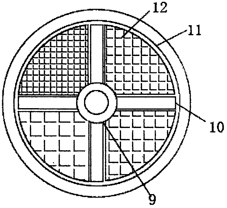
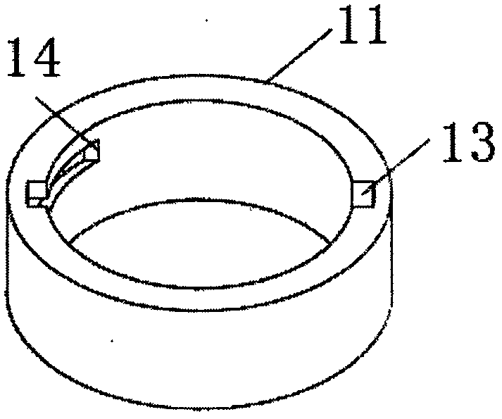
[0020] see Figure 1-3 , the present invention provides a technical solution: a UAV position adjustment device in the air, including a fuselage 1 and a load-bearing plate 11, the outer surface of the fuselage 1 is symmetrically welded vertically on both sides to install the organic arm 2, and the inside of the fuselage 1 A motor 4 slot 3 is provided, and a motor 4 is fixedly installed inside the motor 4 slot 3. The middle part of the lower surface of the motor...


PUM


Abstract

The invention discloses an unmanned aerial vehicle air position adjusting device, which comprises a fuselage and a bearing plate. Arms are symmetrically and vertically welded on the outer surface of the fuselage, the fuselage is internally provided with a motor tank, a motor is internally fixedly mounted in the motor tank, the middle part of the lower surface of the motor is rotatably connected with a middle shaft, the lower surface of the fuselage is provided with a shaft rod groove, and the shaft rod groove is connected with the motor tank; the motor is internally mounted in the fuselage ofthe unmanned aerial vehicle air position adjusting device to drive the rotation of the middle shaft so as to drive the rotation of bottom rotating rods, bearing blocks are arranged between adjacent rotating rods, and the weight of each bearing block is different, so that the position of the center of the fuselage can be adjusted according to the actual situation when the fuselage is in a flight; afixing seat is disposed under the fuselage, and positioning blocks disposed on both sides of the fixing seat pass through sliding grooves symmetrically disposed on both sides of the bearing plate andare clamped on the inner wall of a movable groove.

Description

technical field [0001] The invention relates to the technical field of unmanned aerial vehicles, in particular to an air position adjustment device for unmanned aerial vehicles. Background technique [0002] When the drone is not equipped with other equipment, its center is generally located on the central axis of the fuselage, so as to achieve the balance of the drone during flight. However, due to the different application fields of the drone, the weight of the drone when it is carried There is a large difference, which affects the balance of the UAV during flight. At present, the commonly used method is the counterweight method. The center of the UAV is located at the central axis, but in the prior art, the method of mating is generally to fix the counterweight objects on the upper and lower sides of the fuselage, which itself does not have any adjustment function, which leads to relatively large limitations and cannot To ensure the safety of UAVs during flight, we propo...

Claims


Application Information

Patent Timeline
IPC IPC(8): B64C17/02
CPCB64C17/02
Inventor 倪惠芳
Owner 广西电网有限责任公司梧州供电局
Learn More