Annular sponge wetland garden and construction method thereof

A sponge and wetland technology, which is applied to the annular sponge wetland garden and its construction field, can solve the problems of increasing the construction cost of sponge facilities, large area, difficult construction, etc., and achieves improved rainwater treatment efficiency, small area and convenient construction. Effect

Active Publication Date: 2021-04-20
JIANGSU LONG LEAPING ENG DESIGN
View PDF8 Cites 1 Cited by
  • Summary
  • Abstract
  • Description
  • Claims
  • Application Information

AI Technical Summary

Problems solved by technology

However, the applicant found in practical application that there is a big difference between the water quality of initial rainwater and normal rainwater. For example, in the river channel management, the initial rainwater has been specially treated instead of one size fits all. It can be see

Method used


Image

  • Annular sponge wetland garden and construction method thereof
  • Annular sponge wetland garden and construction method thereof
  • Annular sponge wetland garden and construction method thereof

Examples


Embodiment 1

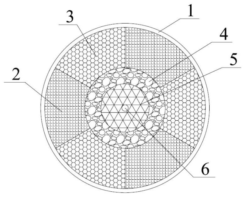
[0055] Such as figure 1 As shown, the present application adopts a ring-shaped sponge wetland garden. The surface of the ring-shaped sponge wetland garden is a circular structure, and rainwater enters the catchment channel 1 along the entire circumference at all angles. And from the outside to the inside are the catchment channel 1, the high load area 2 and the low load area 3, the buffer zone 4, the water storage area 5 and the central well 6.

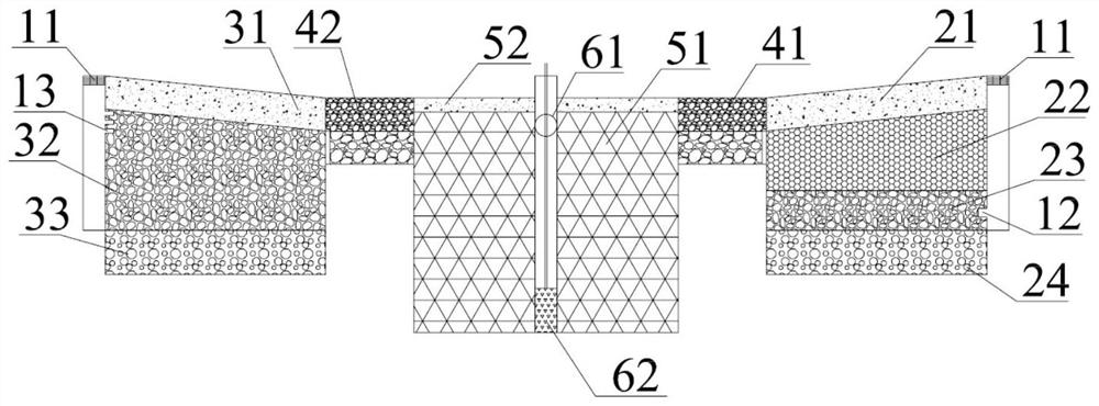
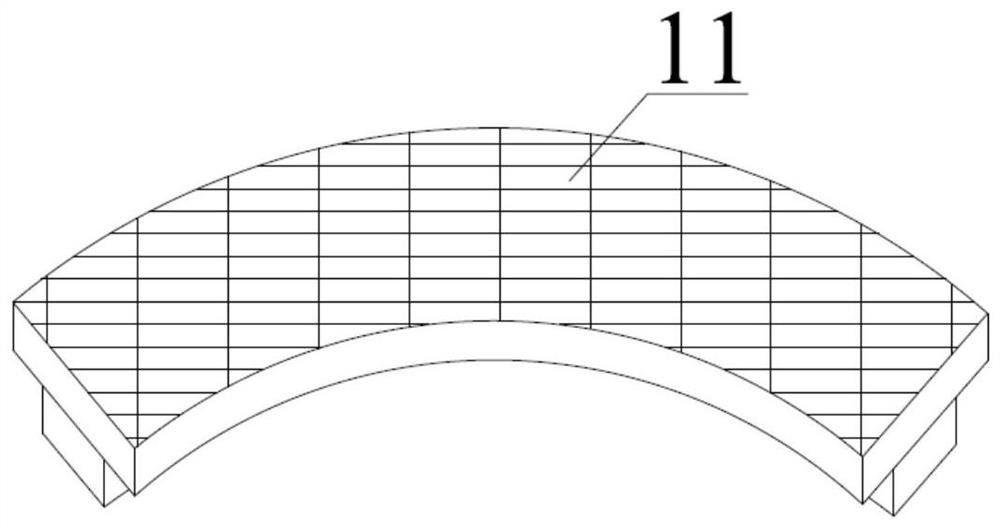
[0056] Drainage channel 1, including the inner cylinder (such as Figure 4 with Figure 5 Shown) and outer cylinder 15 (such as Image 6 As shown), a water collection area is formed between the inner cylinder and the outer cylinder 15; wherein, the inner cylinder is spliced ​​by several sub-tubes, and some of the sub-tubes are provided with an upper water inlet in the upper area Hole 13 (eg Figure 5 shown), the other part of the cylinder is provided with a lower water inlet hole 12 in the lower area (such as Figure 4 shown); th...

Embodiment 2

[0071] A construction method for a ring-shaped sponge wetland garden, following the construction principles of bottom-up, inside-out, first underground and then above-ground, including the following steps:

[0072] Step 1: The foundation pit is excavated from the outside to the inside, excavating in layers according to the design requirements. After the excavation is completed, compact the bottom of the foundation pit separately, and then carry out the construction of the waterproof layer of the overall foundation pit after the degree of compaction reaches more than 95%;

[0073] Step 2: The HDPE film is installed on the slope, and the overall structure should be adopted to avoid hot-melt joints. The inevitable joints should be controlled in the gentle slope area, and the tightness detection of the interface of the film laid in the horizontal position should be strengthened to strictly control the construction Quality, after the HDPE film installation is completed, the next st...


PUM

PropertyMeasurementUnit
Particle sizeaaaaaaaaaa
Depthaaaaaaaaaa

Abstract

The invention belongs to the field of sponge city construction, and relates to an annular sponge wetland garden and a construction method thereof. The annular sponge wetland garden comprises a water collecting channel, a high-load area, a low-load area and a central well, wherein the water collecting channel comprises an inner barrel and an outer barrel; the inner barrel is formed by splicing a plurality of sub-barrels; upper water inlet holes are formed in the upper areas of part of the sub-barrels, and lower water inlet holes are formed in the lower areas of the other part of the sub-barrels; the lower water inlet holes communicate with the lower part of a filter layer of the high-load area; the upper water inlet holes communicate with a filter layer of the low-load area; and the lowest layer of a buffer area communicates with the upper area of an adsorption layer of the high-load area and the upper area of the filter layer of the low-load area. According to the annular sponge wetland garden, rainwater in different periods can be treated in different areas, rainwater collection, a rainwater garden, a rainwater wetland and a water storage module are integrated, and the occupied area of the wetland garden is effectively reduced.

Description

technical field [0001] The invention belongs to the field of sponge city construction and relates to an annular sponge wetland garden and a construction method thereof. Background technique [0002] With the rapid development of sponge city construction, the requirements for sponge facilities in newly built communities are increasing. Technologies such as rainwater infiltration, storage, storage, transmission, and purification are gradually being applied in the construction of communities, parks, squares, etc. [0003] The rainwater process in sponge construction includes rainwater collection, treatment, regulation and storage, reuse or discharge. Related facilities include permeable pavement, rain gardens, rainwater wetlands, bioretention ponds, etc. The division of labor and cooperation between various facilities to achieve related functions. However, the applicant found in practical application that there is a big difference between the water quality of initial rainwater ...

Claims


Application Information

Patent Timeline
IPC IPC(8): E03F1/00A01G9/02E03B3/02E03F5/10
CPCY02A20/108
Inventor 宗媛张瑞斌刘清泉李澄何文江奚道国周乃毕佳佳张盼
Owner JIANGSU LONG LEAPING ENG DESIGN
Why Eureka
Try Eureka