Rotary-knob-type gear shifting device

A gear shifter and knob-type technology, which is applied to components with teeth, belts/chains/gears, mechanical equipment, etc., can solve the problem of poor shifting feel of the user, inability to stop the circumferential stop of the knob assembly, and unreliable Provide etc.

Pending Publication Date: 2018-07-31
LIAONING SHENGJIALUN CONTROL SYST
View PDF0 Cites 0 Cited by
  • Summary
  • Abstract
  • Description
  • Claims
  • Application Information

AI Technical Summary

Problems solved by technology

Due to the limitation of the diameter of the knob assembly, the design space for the length of the bullet and the spring is small, which will cause the spring to not reliably provide the elastic force to elastically limit the bullet in the gear limit groove, and cannot reliably rotate the knob assembly. To the stop gear, resulting in a poor shift feel for the user

Method used


Image

  • Rotary-knob-type gear shifting device
  • Rotary-knob-type gear shifting device
  • Rotary-knob-type gear shifting device

Examples


Embodiment Construction

[0025] The present invention is described in detail below in conjunction with accompanying drawing:

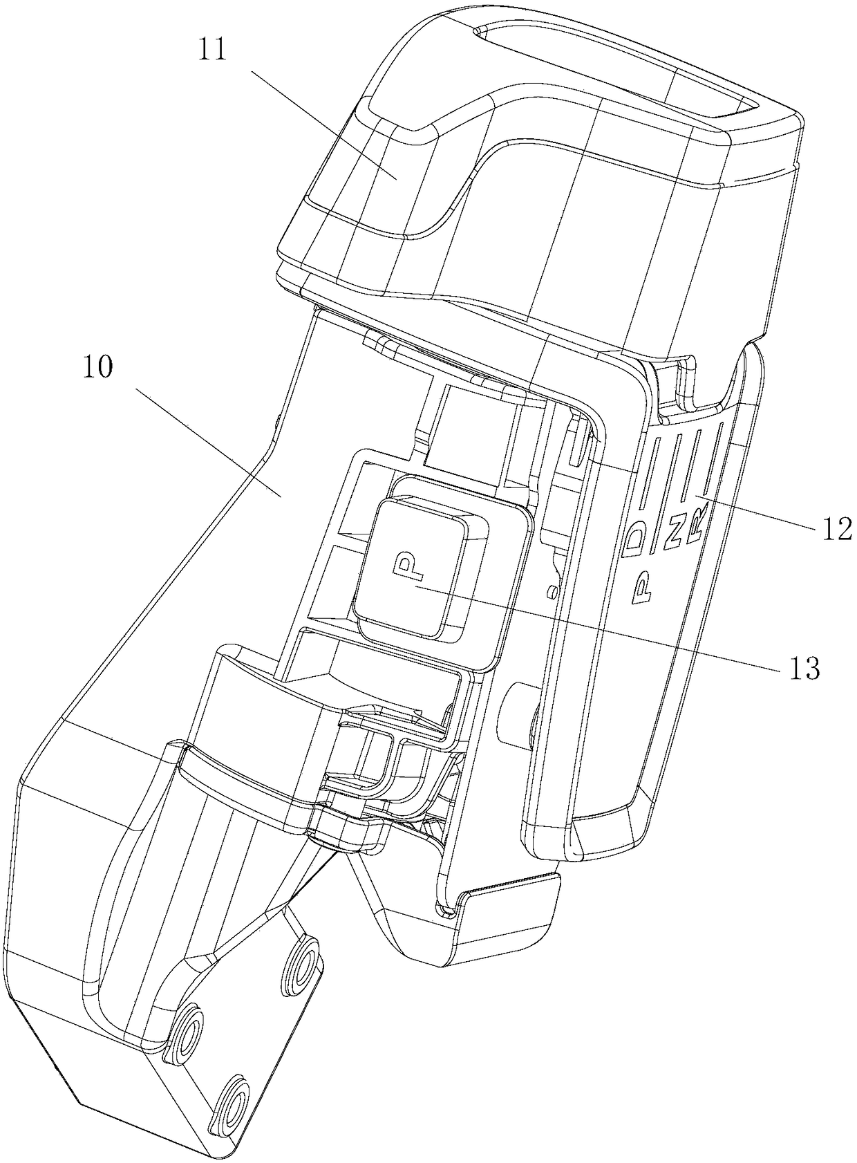
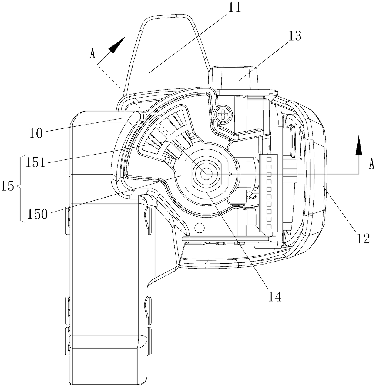
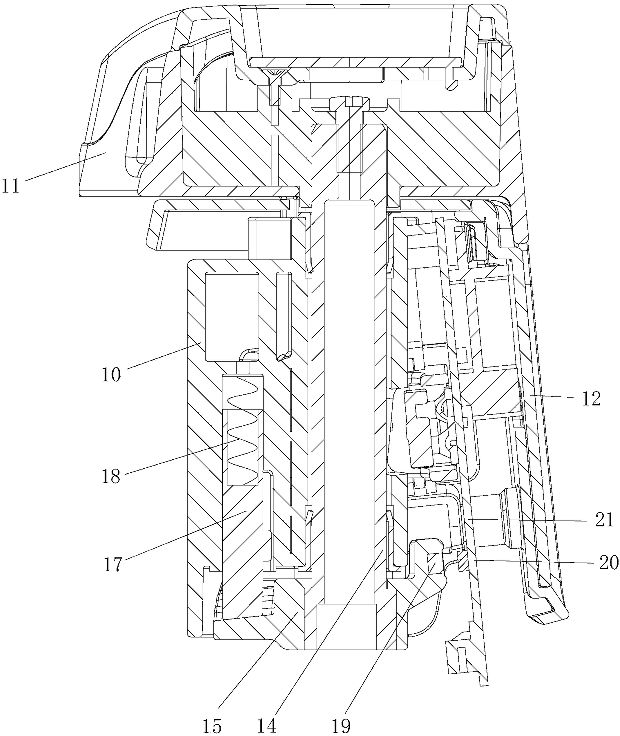
[0026] see Figure 1 to Figure 3 , which is a knob-type shifter in a preferred embodiment provided by the present invention. The knob-type shifter includes a support body 10 , a knob 11 , a connecting piece, a driven wheel 15 , an elastic limit piece, a magnet 19 , a Hall sensor 20 and a circuit board 21 . The knob 11 is rotatably mounted on the support body 10 for operation and rotation by a user. The knob 11 has a starting position and a plurality of gear positions. The knob 11 can be rotated from the initial position to any gear position. When the user needs to switch to one of the gear positions, the knob 11 can be turned from the initial position to the gear position.

[0027] The connecting piece is arranged on the knob 11 . The connecting piece extends toward one axial side of the knob 11 and is connected with the driven wheel 15 . The driven wheel 15 is rotatably...


PUM


Abstract

The invention discloses a rotary-knob-type gear shifting device. The rotary-knob-type gear shifting device comprises a rotary knob, a connecting piece, a driven wheel, and elastic limiting pieces, wherein the rotary knob can be rotated to a plurality of gears; the connecting piece is arranged on the rotary knob and extends towards the axial side of the rotary knob; the driven wheel is arranged onthe side, away from the rotary knob, of a rotating shaft, the rotary knob drives the driven wheel to rotate through the connecting piece, and limiting grooves in one-to-one correspondence to the gearsare formed in the driven wheel; and the elastic limiting pieces are fixedly arranged on one sides of the gear limiting grooves and can be matched with the limiting groove corresponding to the gear when the rotary knob rotates to any gear. In the rotary-knob-type gear shifting device, the driven wheel is connected with the rotary knob through the connecting piece, and the length of the connectingpiece can be set according to the need, so that the driven wheel and the elastic limiting pieces can be arranged away from the rotary knob, and the occupied spaces of the driven wheel and the elasticlimiting pieces are not limited by the inner space of the rotary knob.

Description

technical field [0001] The invention relates to a knob type shifter. Background technique [0002] In the knob-type shifter, the user rotates the knob assembly to different gear positions by turning the knob assembly, and realizes gear shifting by identifying the current position of the knob assembly. A bullet is fixedly installed on the knob assembly. One side of the bullet head is provided with gear position limiting slots corresponding to the gear positions one by one. A spring is arranged on one side of the bullet head away from the direction of the gear position limiting groove. [0003] When the knob assembly is turned, the bullet head turns accordingly. When the knob assembly is rotated to one of the gear positions, the head of the bullet is aligned with the position of the corresponding gear limit slot, and can be limited in the corresponding gear limit slot under the spring force. Through the cooperation of the bullet head and the gear position limiting slot, th...

Claims


Application Information

Patent Timeline
IPC IPC(8): F16H59/08F16H59/12F16H61/24F16H63/40F16H63/42
CPCF16H59/08F16H59/12F16H61/24F16H63/40F16H63/42F16H2059/081F16H2061/247
Inventor 嵇苏美曹晖
Owner LIAONING SHENGJIALUN CONTROL SYST
Why Eureka
Try Eureka