Oxygen concentration detecting device

A detection device, a technology for oxygen concentration, applied in the direction of measurement devices, instruments, scientific instruments, etc., can solve the problems of complexity and inconvenience, and achieve the effect of promoting air circulation

Inactive Publication Date: 2018-07-31
杨文龙
View PDF7 Cites 1 Cited by
  • Summary
  • Abstract
  • Description
  • Claims
  • Application Information

AI Technical Summary

Problems solved by technology

[0005] In order to overcome the shortcomings of the current air concentration detection process that is too complicated and inconvenient to use, the technical problem to be solved by the present invention is to provide an oxygen concentration detection device that can save manpower, is convenient to use, and has accurate inspection

Method used


Image

  • Oxygen concentration detecting device
  • Oxygen concentration detecting device
  • Oxygen concentration detecting device

Examples


Embodiment 1

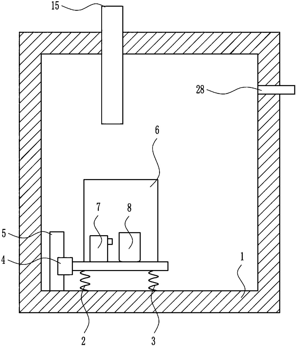
[0027] An oxygen concentration detection device, such as Figure 1-5 As shown, it includes a fixed frame 1, a first spring 2, a second spring 3, a slider 4, a slide rail 5, a box body 6, a lighter 7, a beaker 8, an exhaust pipe 28 and an air inlet pipe 15, and the fixed The lower part of the frame 1 is equipped with a slide rail 5, the right part of the slide rail 5 is slidably installed with a slider 4, the first spring 2 and the second spring 3 are installed between the lower part of the slider 4 and the fixed frame 1, and the upper part of the slider 4 is installed Casing 6 is arranged, and beaker 8 and lighter 7 are installed in casing 6, and air inlet pipe 15 is installed on fixed frame 1 top, and exhaust pipe 28 is installed on fixed frame 1 right part.

Embodiment 2

[0029] An oxygen concentration detection device, such as Figure 1-5 As shown, it includes a fixed frame 1, a first spring 2, a second spring 3, a slider 4, a slide rail 5, a box body 6, a lighter 7, a beaker 8, an exhaust pipe 28 and an air inlet pipe 15, and the fixed The lower part of the frame 1 is equipped with a slide rail 5, the right part of the slide rail 5 is slidably installed with a slider 4, the first spring 2 and the second spring 3 are installed between the lower part of the slider 4 and the fixed frame 1, and the upper part of the slider 4 is installed Casing 6 is arranged, and beaker 8 and lighter 7 are installed in casing 6, and air inlet pipe 15 is installed on fixed frame 1 top, and exhaust pipe 28 is installed on fixed frame 1 right part.

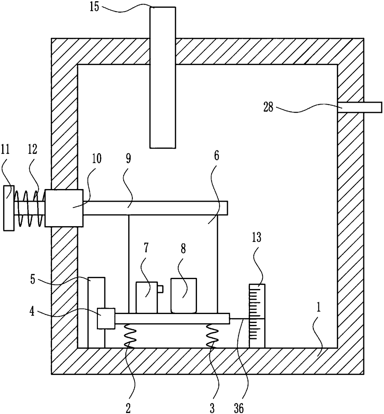
[0030] Also include the first slide bar 9, the first sliding sleeve 10, the first baffle plate 11, the third spring 12, the scale 13 and the pointer 36, the first sliding sleeve 10 is installed on the left part of the f...

Embodiment 3

[0032] An oxygen concentration detection device, such as Figure 1-5 As shown, it includes a fixed frame 1, a first spring 2, a second spring 3, a slider 4, a slide rail 5, a box body 6, a lighter 7, a beaker 8, an exhaust pipe 28 and an air inlet pipe 15, and the fixed The lower part of the frame 1 is equipped with a slide rail 5, the right part of the slide rail 5 is slidably installed with a slider 4, the first spring 2 and the second spring 3 are installed between the lower part of the slider 4 and the fixed frame 1, and the upper part of the slider 4 is installed Casing 6 is arranged, and beaker 8 and lighter 7 are installed in casing 6, and air inlet pipe 15 is installed on fixed frame 1 top, and exhaust pipe 28 is installed on fixed frame 1 right part.

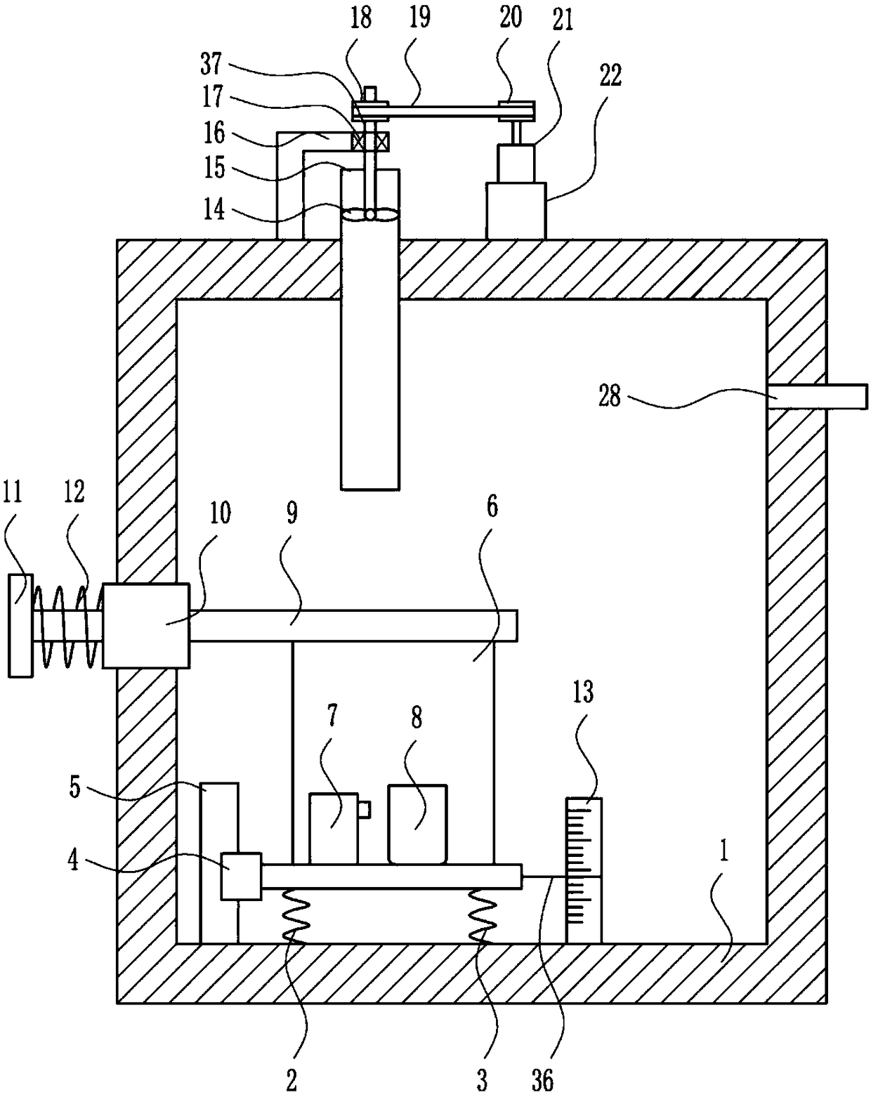
[0033] Also include the first slide bar 9, the first sliding sleeve 10, the first baffle plate 11, the third spring 12, the scale 13 and the pointer 36, the first sliding sleeve 10 is installed on the left part of the f...


PUM


Abstract

The invention relates to a detecting device, in particular relates to an oxygen concentration detecting device. The technical problem to be solved by the present invention is to provide an oxygen concentration detecting device which saves labor, and is convenient to use and accurate in inspection. The oxygen concentration detecting device comprises a fixing frame, a first spring, a second spring,and the like; a sliding rail is installed in the lower part of the fixing frame, a sliding block is arranged on the right side of the sliding rail in a sliding manner, the first spring and the secondspring are installed between the lower part of the sliding block and the fixing frames, a box body is installed on the upper part of the sliding block, a beaker and a fire extinguisher are installed in the box body, an air inlet pipe is installed in the upper part of the fixing frame, and an air exhaust pipe is installed in the right part of the fixing frame. The oxygen concentration detecting device achieves the effects of saving manpower, convenient use and accurate inspection. The oxygen concentration detecting device e can quickly complete the measurement of oxygen concentration in the air, is convenient and safe to use and simple in operation, and saves staff time, and the oxygen concentration detecting device is exquisite in structure, reasonable in design and long in service life.

Description

technical field [0001] The invention relates to a detection device, in particular to an oxygen concentration detection device. Background technique [0002] Environmental protection monitoring takes the lead, and automation and informatization are the premise and guarantee for doing a good job in environmental monitoring. Over the years, while the local economy has developed rapidly, environmental pollution incidents such as water, air, and noise have occurred in various degrees in various regions, which have seriously affected people. quality of life, hindering the sustainable development of the local economy. With the promulgation and implementation of various environmental protection policies and regulations formulated by the state, local governments at all levels are paying more and more attention to environmental governance within their jurisdictions, and at the same time increasing investment in environmental monitoring and emergency monitoring, and planning and instal...

Claims


Application Information

Patent Timeline
Patent Type & Authority Applications(China)
IPC IPC(8): G01N5/00
CPCG01N5/00
Inventor 杨文龙黄瑾婵吴子谦
Owner 杨文龙
Why Eureka
Try Eureka