Connecting rod type sample clamp

A sample holder and connecting rod technology, applied in the field of spectral analysis, can solve the problems of shortening the life of the spring, affecting the use of the instrument, and poor user experience, and achieving the effects of flexible and reliable movement, convenient operation and simple structure

Pending Publication Date: 2018-07-31
FOCUSED PHOTONICS +1
View PDF7 Cites 0 Cited by
  • Summary
  • Abstract
  • Description
  • Claims
  • Application Information

AI Technical Summary

Problems solved by technology

[0003] One is cylinder compression, such as Bruker, ARUN, 8002, etc., but the way of cylinder compression needs to provide one way of air circuit control, and some cylinders are located above the excitation table panel, which not only looks ugly, but also occupies a certain space, affecting Excitation of large samples; In addition, some instruments cover the sample and the sample holder as a whole in order to play a protective role, which makes it difficult to judge whether the sample holder is pressed properly, and the user experience is poor
[0004] The other type is spring compression, such as Spike, M5000, Oxford, etc., but the life of the spring is short, and the friction between the spring and the shaft will also shorten the life of the spring, resulting in frequent failure of the spring, which directly affects the use of the instrument; Moreover, the size of the sample holder with the current spring structure is relatively large, which also affects the excitation of large samples.

Method used


Image

  • Connecting rod type sample clamp

Examples


Embodiment 1

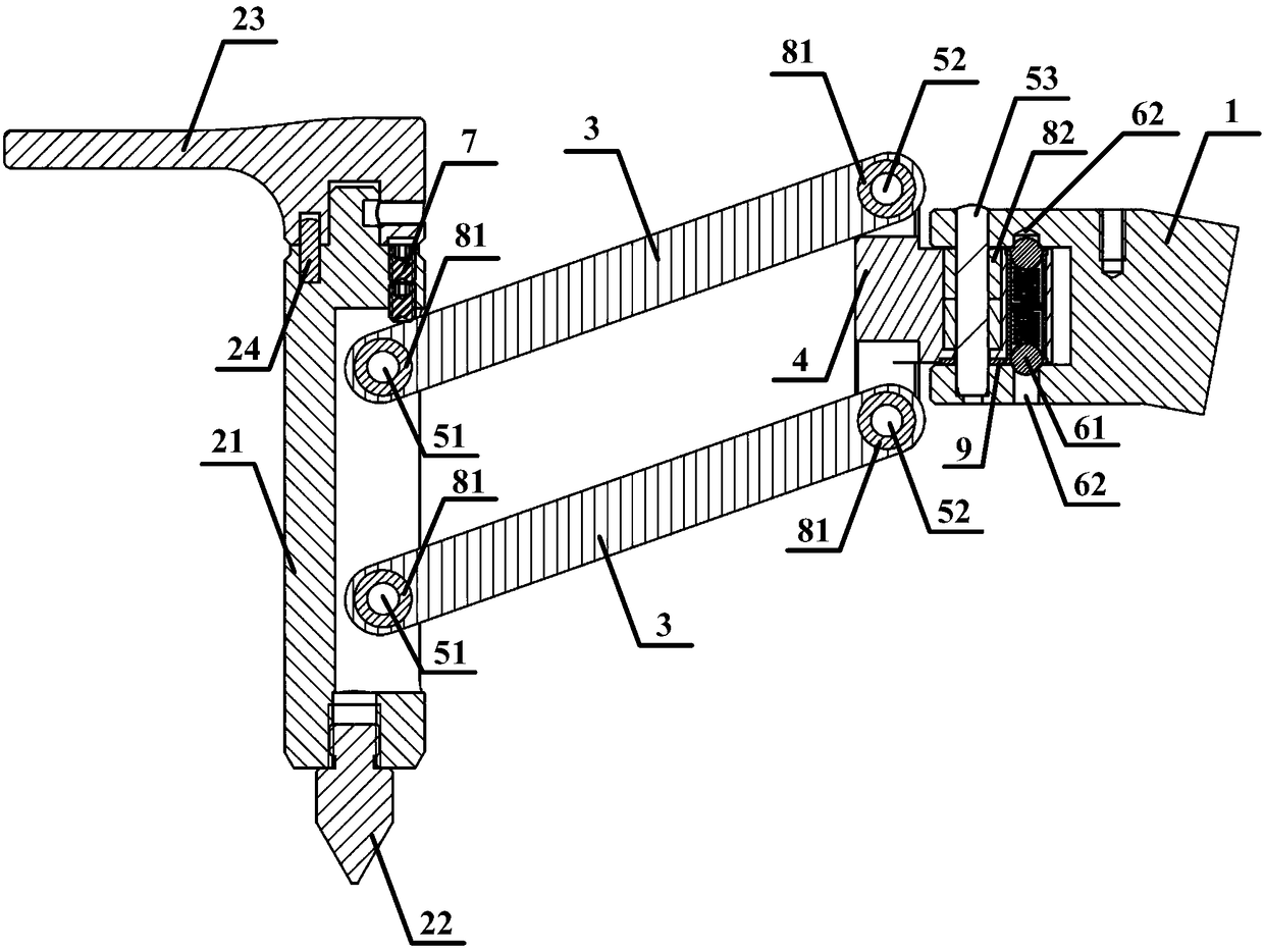
[0034] figure 1 Schematically provides a schematic structural diagram of the link-type sample holder of the present embodiment, as figure 1 As shown, the sample holder includes:

[0035] Mounting seat 1, the mounting seat is used to fix the sample holder on the instrument;

[0036] Pressing rod 21 and pressing head 22, described pressing rod and pressing head are used for compressing sample;

[0037] Connecting rod 3, one end of the connecting rod is connected with the pressure rod through the first rotating shaft 51, and the other end is connected with the rotating rod through the second rotating shaft 52;

[0038] The rotating rod 4 is connected to the mounting base through a third rotating shaft 53 .

[0039] In this embodiment, the connecting rod keeps the pressing rod in a stable vertical state during the movement of the sample holder. Therefore, there are at least two connecting rods to form a stable parallelogram structure. No matter how the sample holder moves, the ...

Embodiment 2

[0058] This embodiment is an application example in which the connecting-rod sample of Embodiment 1 of the present invention is clamped on a direct-reading spectrometer.

[0059] In the application example, the sample clamp is fixed on the direct-reading spectrometer through the mount, and a handle is provided above the pressure rod. The handle and the pressure rod are connected by a positioning pin with a diameter of 3mm×10mm. There is a space for the connecting rod to move up and down. There is a screw above the groove of the pressure rod, and the lower end of the screw extends into the groove of the pressure rod to limit the lowest position of the sample holder. The screw adopts a set screw with a hexagonal socket. When a different minimum limit is required, it can be realized by adjusting the screw; the conduction between the indenter and the mounting seat ensures that the direct reading spectrometer can detect whether the indenter touches the sample through the mounting se...


PUM


Abstract

The invention relates to a connecting rod type sample clamp. The connecting rod type sample clamp comprises an installation pedestal, a pressing rod and a pressing head, a connecting rod, and a rotating rod; the installation pedestal is used for fixing the connecting rod type sample clamp onto instrument; the pressing rod and the pressing head are used for compaction of samples; one end of the connecting rod is connected with the pressing rod through a first rotating shaft, and the other end is connected with the rotating shaft through a second rotating shaft; the rotating shaft is connected with the installation pedestal through a third rotating shaft. The connecting rod type sample clamp is simple in structure, is flexible, and is reliable, and maintenance is not needed.

Description

technical field [0001] The invention relates to the field of spectroscopic analysis, in particular to a link-type sample clamp applied to spectrometer sample clamping. Background technique [0002] At present, there are two main types of clamping methods for direct reading spectrometers on the market: [0003] One is cylinder compression, such as Bruker, ARUN, 8002, etc., but the way of cylinder compression needs to provide one way of air circuit control, and some cylinders are located above the excitation table panel, which not only looks ugly, but also occupies a certain space, affecting Excitation of large samples; In addition, some instruments cover the sample and the sample holder as a whole in order to play a protective role, which makes it difficult to judge whether the sample holder is pressed properly, and the user experience is poor. [0004] The other type is spring compression, such as Spike, M5000, Oxford, etc., but the life of the spring is short, and the fric...

Claims


Application Information

Patent Timeline
Patent Type & Authority Applications(China)
IPC IPC(8): G01N21/01
CPCG01N21/01
Inventor 吴锋明徐桔红苏德怀张英王庆祥许辉平潘言涛张博书岳立洪波
Owner FOCUSED PHOTONICS
Why Eureka
Try Eureka