Method for calculating ionization absorbed dose of radiation sensitive part based on absorbed dose depth distribution

An absorbed dose and radiation-sensitive technology, which is applied in dosimeters and other directions, can solve the problems of complex calculation and long time consumption, and achieve the effect of reducing calculation time, simple steps and easy operation

Inactive Publication Date: 2018-07-31
HARBIN INST OF TECH
View PDF0 Cites 0 Cited by
  • Summary
  • Abstract
  • Description
  • Claims
  • Application Information

AI Technical Summary

Problems solved by technology

[0005] In order to solve the problem of complex and time-consuming calculation of ionized absorbed dose at radiation-sensitive parts in the prior art, the present invention provides a method for calculating ionized absorbed dose at radiation-sensitive parts based on absorbed dose depth distribution

Method used


Image

  • Method for calculating ionization absorbed dose of radiation sensitive part based on absorbed dose depth distribution
  • Method for calculating ionization absorbed dose of radiation sensitive part based on absorbed dose depth distribution
  • Method for calculating ionization absorbed dose of radiation sensitive part based on absorbed dose depth distribution

Examples


specific Embodiment approach 1

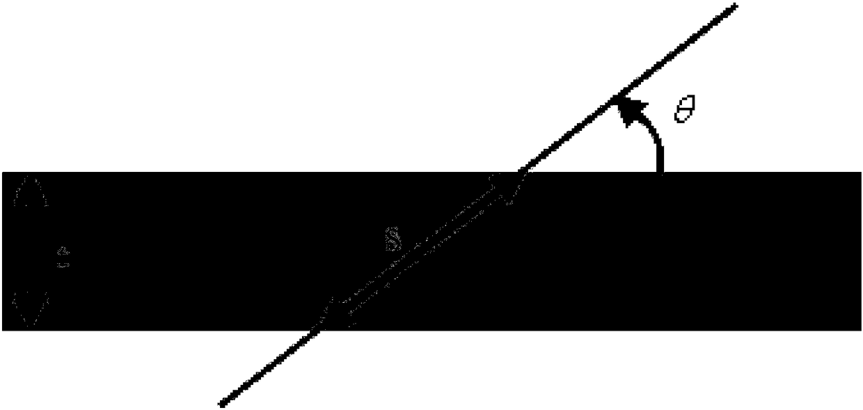
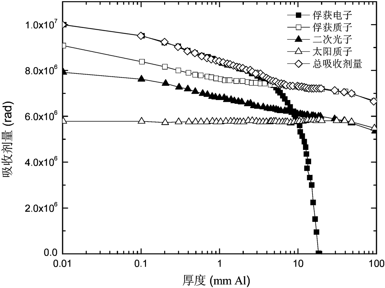
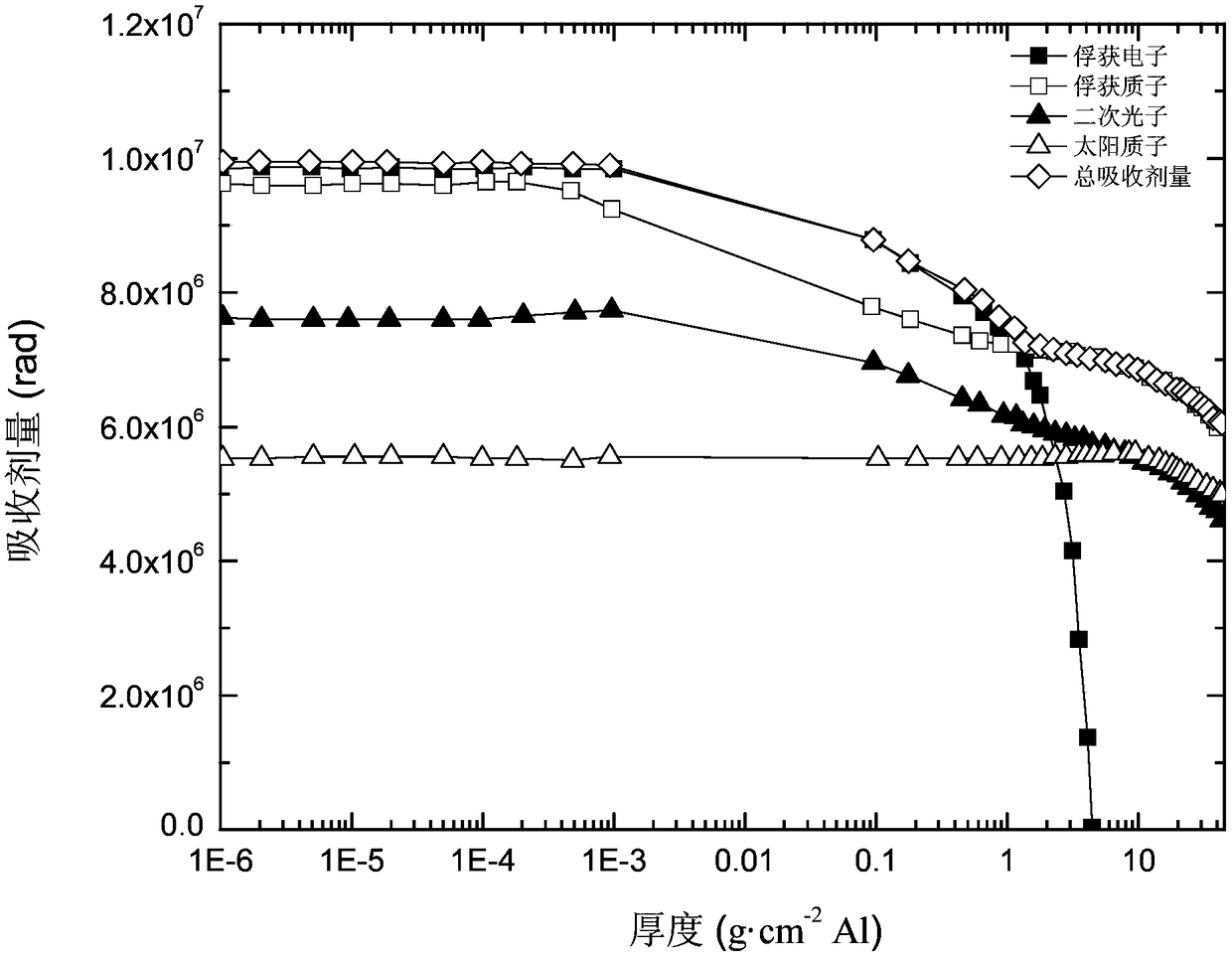
[0026] Specific implementation mode one: combine figure 1 , figure 2 , image 3 , Figure 4 To illustrate this embodiment, the method for calculating the ionized absorbed dose of radiation-sensitive parts based on the absorbed dose depth distribution given in this embodiment specifically includes the following steps:

[0027] Due to the different specific structures, the unidirectional absorbed dose depth distribution will lead to different effects. Different types of incident particles (especially different types of charged particles) will simultaneously generate ionization and displacement damage during the transportation of materials and devices. When ionization damage occurs, it will cause a large number of electron-hole pairs in an instant. In order to accurately calculate the depth distribution of ionized absorbed dose, it is necessary to consider the influence of the relative position of the target and the incident particle angle, such as figure 1 shown.

[0028]...

specific Embodiment approach 2

[0038] Specific embodiment 2: The difference between this embodiment and specific embodiment 1 is that in step 5, the equivalent thickness x of region i i The calculation process is:

[0039]

[0040] where ρ j Indicates the density of the jth material, t j Indicates the thickness of the jth material, j∈[1,M].

[0041] Other steps and parameters are the same as those in the first embodiment.

specific Embodiment approach 3

[0042] Specific embodiment three: the difference between this embodiment and specific embodiment one or two is that in step seven, D(x i ) into equivalent thickness x i The corresponding one-way absorbed dose D'(x i ) The specific process is:

[0043] D'(x i )=D(x i ) / 4π.

[0044] Other steps and parameters are the same as those in Embodiment 1 or 2.


PUM


Abstract

The invention provides a method for calculating the ionization absorbed dose of a radiation sensitive part based on absorbed dose depth distribution, and belongs to the technical field of spatial environment effect and nuclear science and application. The method comprises the steps: selecting a material with the known one-dimensional ionization absorbed dose depth distribution, and converting theabsorbed dose depth distribution of the material into the distribution of absorbed dose with equivalent depth; carrying out the regional dividing of a structure where the radiation sensitive part is located, determining the material types of all regions, the material thicknesses of all regions and the maximum degree of the connection lines between the radiation sensitive part and the regions; converting the thicknesses of the materials of all regions into equivalent thicknesses, determining the absorbed dose and unidirectional absorbed dose at each equivalent thickness, and finally calculatingand obtaining the ionization absorbed dose of a sensitive part in the structure. The method solves problems in the prior art that the calculation of the ionization absorbed dose of the radiation sensitive part is complex and the consumed time is long. The method can be used for quickly evaluating the ionization absorbed dose of complex structures, such as a spacecraft.

Description

technical field [0001] The invention relates to a method for calculating the ionized absorbed dose of radiation-sensitive parts, and belongs to the field of space environment effect, nuclear science and application technology. Background technique [0002] Absorbed dose refers to the energy absorbed by a unit mass of material after being irradiated. The strict definition of absorbed dose is the quotient obtained by dividing the average energy dE given by radiation to a material with a mass of dm divided by dm. It is represented by the symbol D and the unit is Gray ( Gy). Spacecraft orbiting in space will be affected by various environmental factors, such as particle radiation, microgravity, and atomic oxygen. With the rapid development of electronic technology, the application of electronic components is becoming more and more extensive. Electronic devices are widely used in satellites, spacecraft and space shuttles to achieve various functions. For electronic devices, pa...

Claims


Application Information

Patent Timeline
IPC IPC(8): G01T1/02
CPCG01T1/02
Inventor 李兴冀刘超铭杨剑群吕钢刘勇
Owner HARBIN INST OF TECH
Why Eureka
Try Eureka