Door locking device

A technology for door locks and car doors, which is applied in doors, building locks, vehicle locks, etc. It can solve problems such as difficult engagement of the engaging ends and complicated assembly operations, and achieve the effect of simplifying assembly operations and increasing assembly speed

Active Publication Date: 2018-07-31
MITSUI KINZOKU ACT
View PDF9 Cites 0 Cited by
  • Summary
  • Abstract
  • Description
  • Claims
  • Application Information

AI Technical Summary

Problems solved by technology

[0008] Therefore, when the engaging end of the wire member is attached to the engaging receiving portion of the handle link, the handle link changes position after being rotated

Method used


Image

  • Door locking device
  • Door locking device
  • Door locking device

Examples


Example Embodiment

[0034] Hereinafter, a preferred embodiment of the door lock device of the present invention will be described in detail with reference to the drawings.

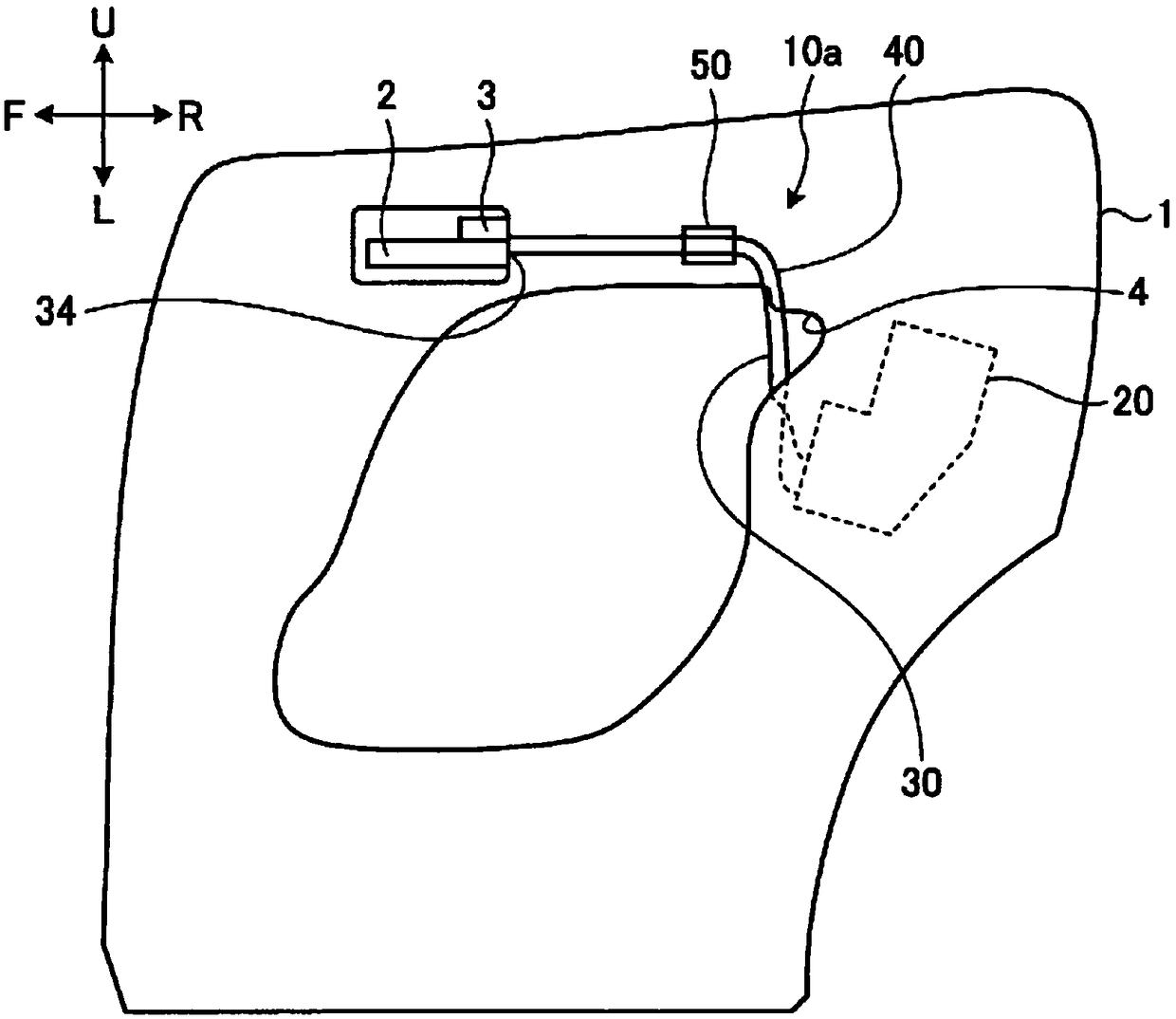
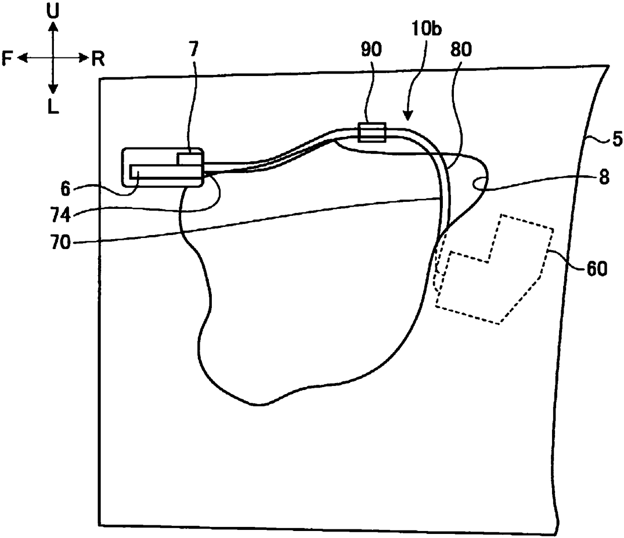
[0035] figure 1 with figure 2 Each is an explanatory diagram showing the door lock device according to the embodiment of the present invention. The door lock device exemplified here uses a four-wheeled vehicle with two front and rear side doors on the left and right sides of the vehicle. figure 1 An example of a device arranged on the rear of the right side of the vehicle with a front hinge mounted on the rear door, figure 2 An example of a device in which the front hinge is installed on the front door is arranged in front of the right side of the vehicle. Below, first explain the installation in figure 1 The door lock device on the rear door (hereinafter also referred to as the rear door lock device) 10a is shown.

[0036] The rear door lock device 10 a includes a rear door lock mechanism 20 and a rear wire holding member (hold...


PUM


Abstract

A door locking device (10a) in which a handle link lever (22) is rotatably installed in the interior of a housing (21), the handle link lever (22) moving from a normal position to a release position when the engagement end (31) of a first wire member (30) for linking the gap with the door handle (2) of a door is engaged, and the door handle (2) is operated in the direction for releasing the door,wherein the housing (21) is provided with a restricting member (25) such that the handle link lever (22) is disposed in a restricted position on the opposite side from a release position, using the normal position as a reference, before being engaged with the engagement end (31), whereby the handle link lever (22) is restricted from rotating to the normal position, and when the handle link lever (22) is engaged with the engagement end (31) and the other end of the first wire member (30) on the opposite side from the engagement end (31) is engaged with the door handle (2), the handle link lever(22) is permitted to be disposed in the normal position.

Description

technical field [0001] The present invention relates to a door lock device. Background technique [0002] The door lock device loaded on the vehicle is equipped with a locking mechanism inside the housing, and is rotatably equipped with a handle link and a locking lever for switching the state of the locking mechanism. A metal wire member is engaged with the handle connecting rod to make it interlock with the door handle, and a metal wire member is engaged with the lock rod to make it interlock with the lock knob. [0003] In this kind of door lock device, the lock lever is arranged in the unlocked position by the operation of the lock knob, and when the door handle is operated from the above state, the handle link moves to the open position, the latch mechanism switches to the unlocked state, and the door lock is closed. The car door can be opened (for example, refer to Patent Document 1). [0004] prior art literature [0005] Patent Document 1: Japanese Patent Laid-Ope...

Claims


Application Information

Patent Timeline
IPC IPC(8): E05B79/22B60J5/00E05B79/08E05B79/20
CPCB60J5/00E05B79/08E05B79/20E05B79/22
Inventor 木村俊太郎
Owner MITSUI KINZOKU ACT
Why Eureka
Try Eureka