Steel collar assembly capable of being driven to rotate and supported by roller

A technology of steel rings and rollers, applied in the field of rotating steel ring components, can solve the problem that the speed of traveler and steel ring cannot be greatly improved, and achieve the effect of reducing the relative speed of motion

Pending Publication Date: 2018-08-03
JINGWEI TEXTILE MASCH CO LTD
View PDF4 Cites 1 Cited by
  • Summary
  • Abstract
  • Description
  • Claims
  • Application Information

AI Technical Summary

Problems solved by technology

[0004] In view of this, the object of the present invention is to aim at a rotating steel ring assembly supported by rollers, aiming at overcoming the defect that the traveler and the steel ring in the yarn forming system of the current spinning frame cannot be greatly improved.

Method used


Image

  • Steel collar assembly capable of being driven to rotate and supported by roller
  • Steel collar assembly capable of being driven to rotate and supported by roller
  • Steel collar assembly capable of being driven to rotate and supported by roller

Examples


Embodiment Construction

[0022] It should be noted that, in the case of no conflict, the embodiments in the present application and the features in the embodiments can be combined with each other. The present invention will be described in detail below with reference to the accompanying drawings and examples.

[0023] In order to enable those skilled in the art to better understand the solution of the present application, the technical solution in the embodiment of the application will be clearly and completely described below in conjunction with the accompanying drawings in the embodiment of the application. Obviously, the described embodiment is only It is an embodiment of a part of the application, but not all of the embodiments. Based on the embodiments in this application, all other embodiments obtained by persons of ordinary skill in the art without creative efforts shall fall within the scope of protection of this application.

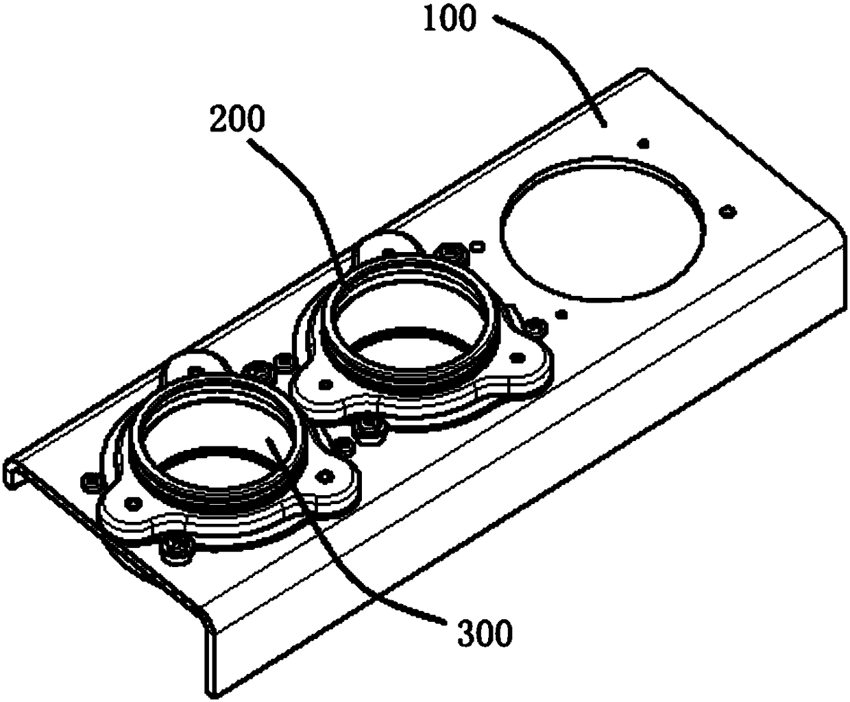
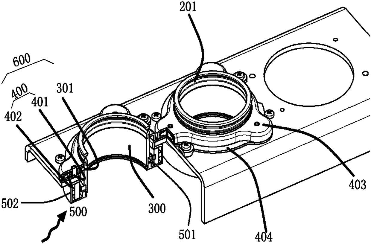
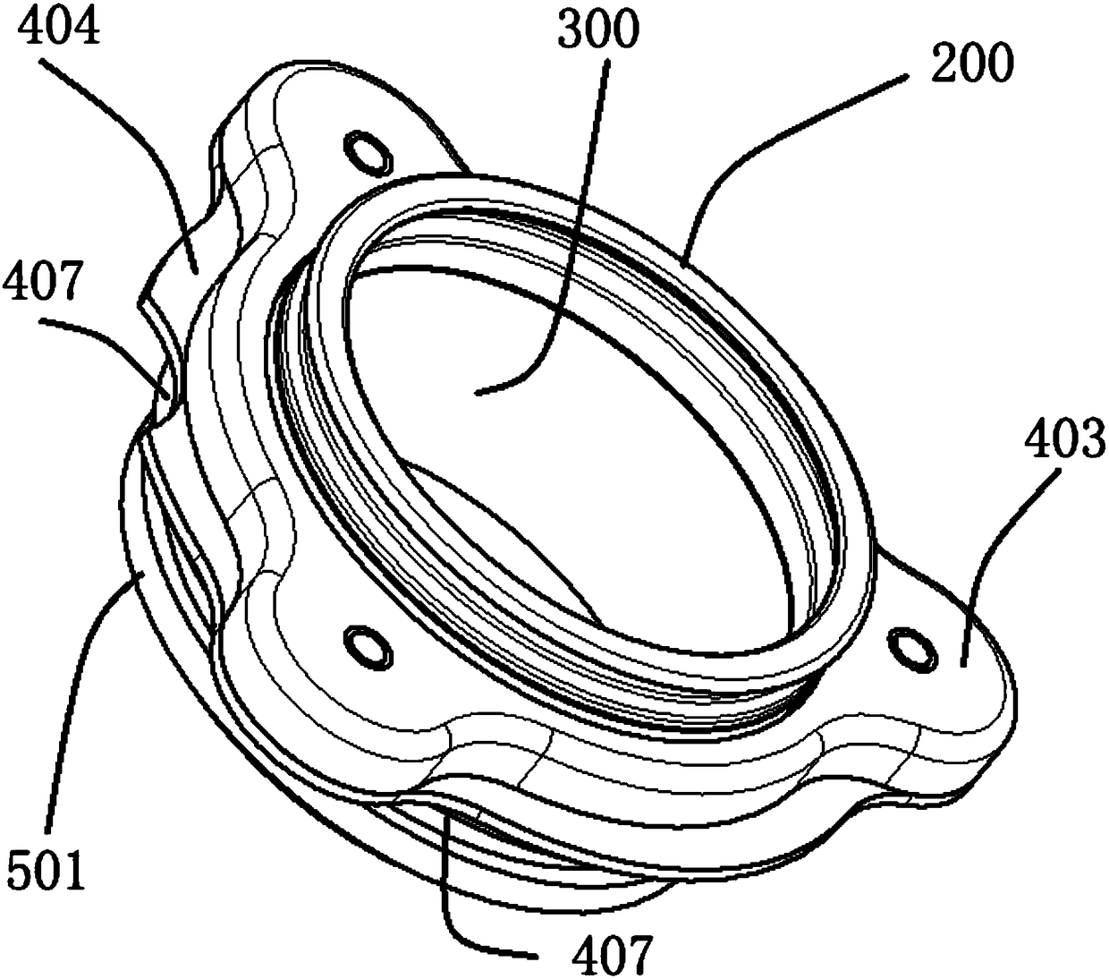
[0024] The structural core of the steel ring assembly supported b...


PUM


Abstract

The invention relates to a steel collar assembly capable of being driven to rotate and supported by a roller. The steel collar assembly comprises a steel collar plate, a steel collar, a steel collar supporting part, roller combination parts and a driving motor assembly. The upper surface of the steel collar plate is provided with three roller combination parts which are on the same plane and are evenly distributed relative to a steel collar center line, the three roller combination parts and the steel collar supporting part disposed on the lower portion of the steel collar are supported through a roller path and matched to form a rotating assembly; the driving motor assembly includes a rotor and a stator assembly, and after the stator assembly and the rotor are fixed, the rotating assemblyis driven to rotate to drive the steel collar to rotate. According to the steel collar assembly, during spinning, since the rotation of the steel collar is the rotary movement in the same direction as a steel wire ring, the rotary movement of the steel collar replaces most of circular motion of the steel wire ring on the steel collar, so that the relative movement speed between the steel wire ring and the steel collar is reduced, and the circular motion speed of the steel wire ring can meet the high-speed operation of a spindle during the spinning process.

Description

technical field [0001] The invention belongs to the field of spinning frame spinning, and in particular relates to a driven and rotatable steel ring assembly supported by rollers, in particular to a self-rotating and controllable rotating steel ring assembly directly driven by a motor. Background technique [0002] With the continuous improvement of the spinning spindle speed of the spinning frame, higher requirements are put forward for the performance of the steel ring and traveler system in the yarn forming system. [0003] At present, the speed of the traveler on the steel ring is generally above 18,000 rpm. When the speed of the traveler continues to increase, due to the influence of various factors such as the material of the traveler, centrifugal force, friction, and pressure during movement, the steel The improvement of the speed of the traveler on the collar is greatly restricted, and the yarn is often burned due to the heat generated by the high-speed rotation of t...

Claims


Application Information

Patent Timeline
Patent Type & Authority Applications(China)
IPC IPC(8): D01H7/56D01H7/58
CPCD01H7/56D01H7/58
Inventor 张新民李增润李晋榆张建香程芝芳
Owner JINGWEI TEXTILE MASCH CO LTD
Why Eureka
Try Eureka