Clamp special for nanoindenter

A technology of nano-indentation instrument and special fixture, which is applied in the direction of instruments, scientific instruments, measuring devices, etc. It can solve the problems of no specific fixture, damage the workpiece, and affect the analysis results of material mechanics, so as to improve accuracy and flexibility, clamp The effect of tightness and uniform force, simple structure of the device

Active Publication Date: 2018-01-05
UNIV OF SHANGHAI FOR SCI & TECH
View PDF8 Cites 8 Cited by
  • Summary
  • Abstract
  • Description
  • Claims
  • Application Information

AI Technical Summary

Problems solved by technology

At present, there are several problems in the nanoindentation experiment process: (1) The commonly used nanoindentation instrument does not have a specific fixture. At present, 502 bonding or screw clamping are often used to fix the workpiece to be tested on the test table.
If the 502 bonding method is used, after the experiment is completed, the workpiece may be damaged when the workpiece is separated with a blade, and the residual colloid may affect the surface morphology of the workpiece
The screw clamping method cannot ensure uniform force on the surface of the workpiece. If the clamping of the workpiece is too tight, there may be a gap between the bottom of the workpiece and the platform; if the clamping is too loose, it may cause a slight movement of the workpiece during the movement of the indenter.
The clamping force of the fixture on the workpiece will directly affect the contact stiffness between the indenter and the workpiece, which will seriously affect the mechanical analysis results of the material; (2) the nano-indentation test cannot be applied to the test of the workpiece with an inclination angle; (3) it cannot be flexible Realize multi-directional testing on the surface of the workpiece. After each test is completed, the position of the workpiece needs to be readjusted to achieve another directional test.

Method used


Image

  • Clamp special for nanoindenter
  • Clamp special for nanoindenter
  • Clamp special for nanoindenter

Examples


Embodiment Construction

[0017] The present invention will be further described below in conjunction with the accompanying drawings and embodiments.

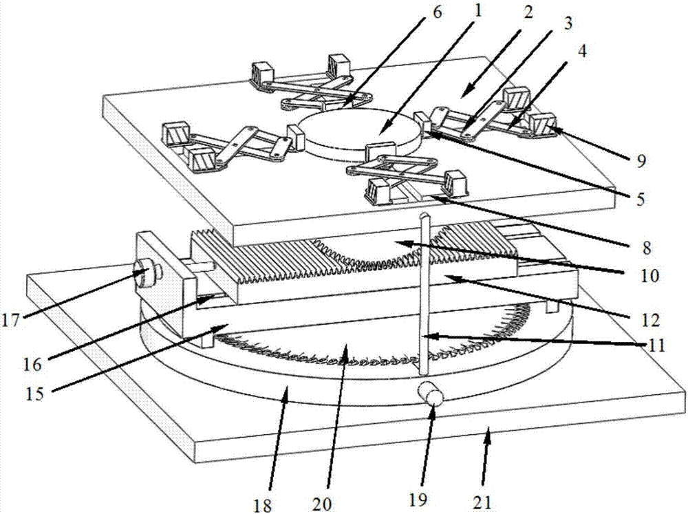
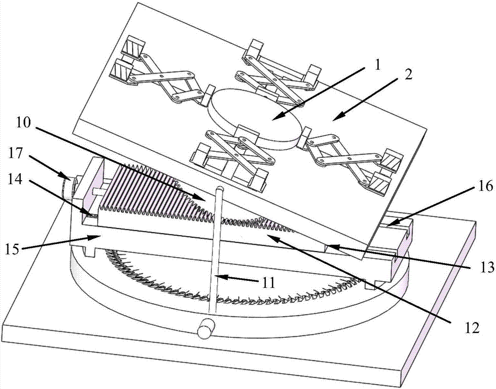
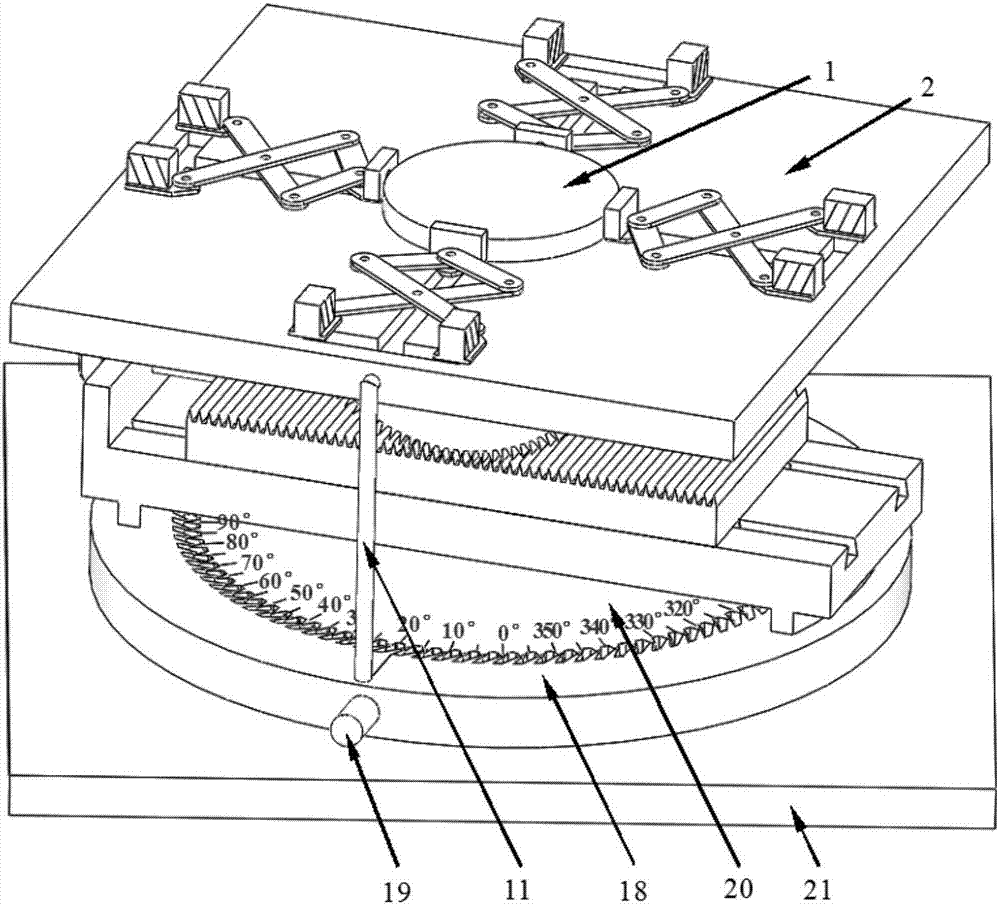
[0018] Such as Figure 1 to Figure 3 As shown, the special fixture for nano-indentation instrument of the present invention is mainly composed of workpiece support plate 2, telescopic chute 3, telescopic frame 4, workpiece clamping block 5, piezoelectric sensor 6, telescopic slider 7, adjustment chute 8, Electromagnet 9, tilting gear 10, rotating support frame 11, tilting rack 12, moving slide bar 13, spring 14, rack rack 15, moving chute 16, micrometer 17, rotating disc 18, rotating handle 19, fixed circle Disk 20, fixture base 21 etc. composition.

[0019] On the workpiece support plate 2, four telescopic frames 4 are evenly distributed along the circumferential direction of the workpiece 1 to be measured. The top of the telescopic frame 4 is connected with a workpiece clamping block 5, and a piezoelectric sensor 6 is placed outside the workpiece cla...


PUM


Abstract

The invention relates to a clamp special for a nanoindenter. The clamp comprises the following components: four telescoping racks and workpiece clamping blocks are arranged on the upper surface of a workpiece supporting plate, the bottom parts of the telescoping racks are provided with telescoping slide blocks, and the workpiece supporting blocks and the telescoping slide blocks are embedded in atelescoping slide way; the tail ends of the telescoping racks are provided with electromagnets, an inclined gear is arranged below the workpiece supporting plate, and rotation supporting racks are arranged at the side of the workpiece supporting plate; the inclined gear and an inclined tooth bar are connected in engagement, the bottom of the inclined tooth bar is connected to a movable slide way by a movable slide bar, the slide bar is internally provided with a spring, and the end of a micrometer is connected to an inclined tooth bar in contact connection; the rotation supporting rack bottompart and a tooth bar rack are fixed at a rotating disk at the lower part; the inner side of the rotating disk is provided with gear teeth with inclination angles, the outside of a fixed disk is provided with uniformly distributed gear teeth, and the rotating disk is connected to the fixed disk in engagement connection through gear teeth. The clamp has simple operation, can realize multi-freedom motion of the workpiece, and ensures good contact between a pressure head and a workpiece to be measured in the working process of the nanoindenter with accurate and reliable experiment results.

Description

technical field [0001] The invention relates to a nano-indentation instrument, in particular to a special fixture for a nano-indentation instrument, and belongs to the technical field of nano-indentation instruments. Background technique [0002] Nanoindentation instrument is mainly used for testing the mechanical properties of micro-nano scale materials. During the working process of the nano indenter, the indenter acts on the surface of the workpiece to be tested with a certain load to create an indentation with a specific shape and size. The hardness and elastic modulus of the material are analyzed through the curve of the pressure and the indentation depth in the unloading stage. properties such as volume, contact stiffness, creep, fracture toughness, storage modulus, and loss modulus. See Rong Junmei, Chai Guozhong, Hao Weina. Research on the mechanical properties of thin films based on nanoindentation technology and finite element simulation[J]. Journal of Zhejiang Un...

Claims


Application Information

Patent Timeline
Patent Type & Authority Applications(China)
IPC IPC(8): G01N3/04G01N3/42
Inventor 叶卉姜晨汪中厚
Owner UNIV OF SHANGHAI FOR SCI & TECH
Why Eureka
Try Eureka