Eureka AIR delivers breakthrough ideas for toughest innovation challenges, trusted by R&D personnel around the world.

Micro-texture radial vibration auxiliary electrolytic machining method and device for inner wall of rotary body of thin-wall part

A technology of radial vibration and processing method, which is applied in the direction of electric processing equipment, electrochemical processing equipment, accessory devices, etc., can solve the problems of low processing performance and difficult discharge of processed products, so as to improve processing accuracy, reduce stray corrosion, The effect of short preparation cycle

Pending Publication Date: 2019-08-09
ZHEJIANG UNIV OF TECH
View PDF0 Cites 8 Cited by
  • Summary
  • Abstract
  • Description
  • Claims
  • Application Information

AI Technical Summary

Problems solved by technology

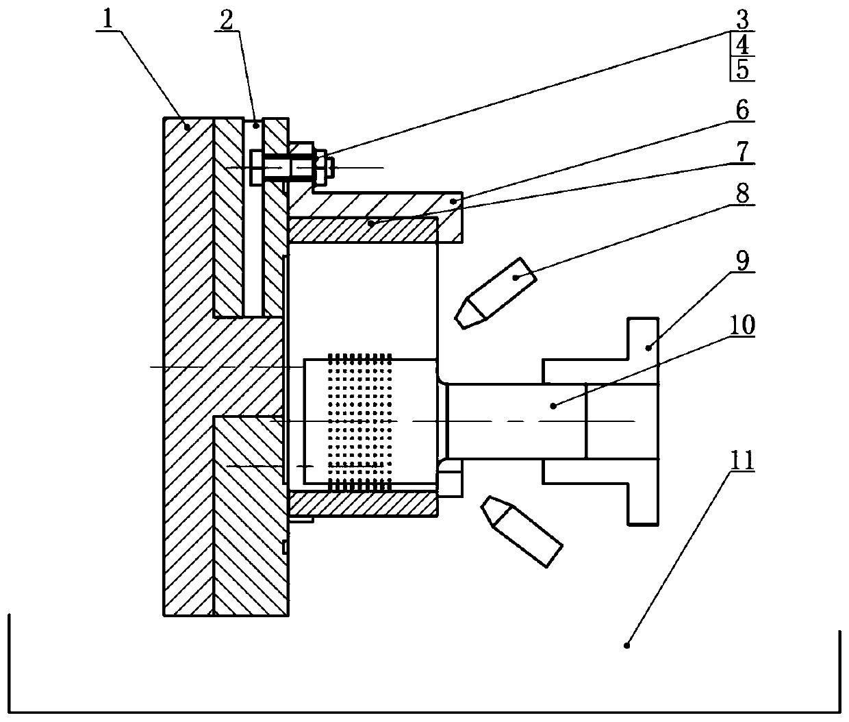
[0003] In order to overcome the shortcomings of difficult discharge of processed products and low processing performance in the existing processing method of micro-texture on the inner wall of a thin-walled rotary, the present invention provides a radial vibration-assisted electrolytic machining method and The device improves the localization, stability, precision and efficiency of micro-texture processing on the inner wall of the rotary

Method used


Image

  • Micro-texture radial vibration auxiliary electrolytic machining method and device for inner wall of rotary body of thin-wall part
  • Micro-texture radial vibration auxiliary electrolytic machining method and device for inner wall of rotary body of thin-wall part
  • Micro-texture radial vibration auxiliary electrolytic machining method and device for inner wall of rotary body of thin-wall part

Examples


Embodiment Construction

[0021] The present invention will be further described below in conjunction with the accompanying drawings.

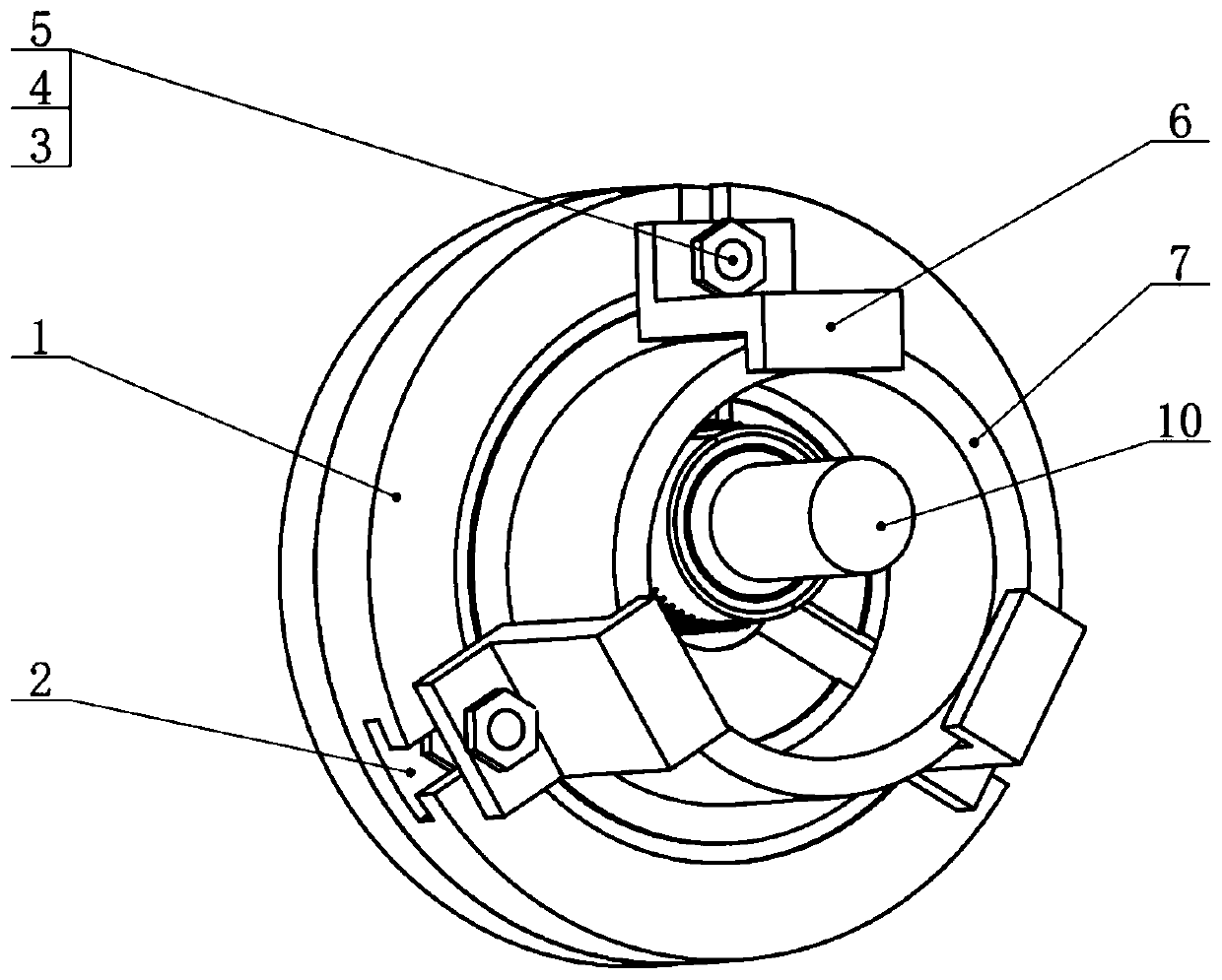
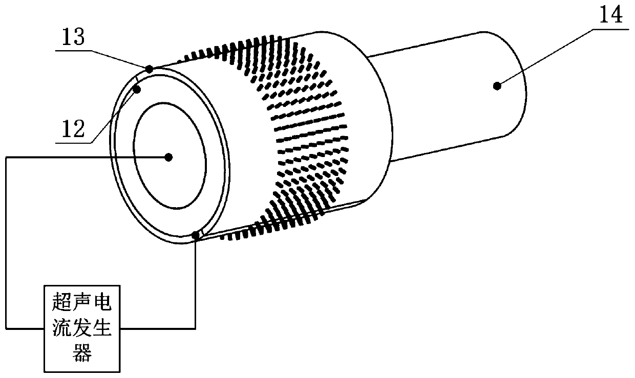
[0022] refer to Figure 1 to Figure 4 , a radial vibration-assisted electrolytic machining method for micro-textured internal walls of a thin-walled part, wherein the cathode of a tool capable of radial vibration with a micro-convex texture on the surface is connected to the negative pole of a power supply, and the cathode of the tool is connected to an ultrasonic current generator The thin-walled rotary workpiece is connected to the positive pole of the power supply, and the columnar electrodes on the tool cathode are arranged in a linear array; the electrolyte enters the reaction area between the tool cathode and the workpiece through the liquid supply pipe, and participates in the electrochemical reaction between the tool cathode and the workpiece. Response: The machine tool spindle drives the tool cathode to move along the circumferential direction according to the...


PUM


Abstract

The invention relates to a micro-texture radial vibration auxiliary electrolytic machining method for the inner wall of a rotary body of a thin-wall part. The method is characterized in that a tool cathode with a micro-boss texture on the surface and capable of doing radial vibration is connected with a negative electrode of the power supply, the tool cathode is connected with an ultrasonic current generator, a thin-wall rotary body workpiece is connected with a positive electrode of the power supply, and the columnar electrode on the tool cathode is arranged in a linear array mode; an electrolyte enters a reaction area between the tool cathode and the workpiece through a liquid supply pipe; a machine tool spindle drives the tool cathode to horizontally move in the peripheral direction according to a preset trajectory, a certain machining gap is reserved between the workpiece and the columnar electrodes on the tool cathode, the machine tool spindle drives the tool cathode to do autorotation motion, and the tool cathode connected with the ultrasonic current generator is used for constructing an ultrasonic energy field; the electrolyte flowing out at a high speed is sprayed onto theworkpiece to obtain the required machining morphology. The invention further provides an micro-texture radial vibration auxiliary electrolytic machining device for the inner wall of the rotary body ofthe thin-wall part. According to the method and the device, the centering property, the stability, the precision and the efficiency for machining the micro-texture of the inner wall of the rotary body are improved.

Description

technical field [0001] The invention belongs to the field of electrolytic processing assisted by radial ultrasonic energy field of low-voltage, high-electrolyte flow-velocity jet, and in particular relates to a method and device for assisted electrolytic processing by radial vibration of micro-texture on the inner wall of a thin-walled rotating body. Background technique [0002] Microstructures are widely used in aviation, aerospace, automobiles, electronics, molds, chemical fibers and other fields to improve product performance. The methods of surface processing micro-texture mainly include mechanical processing, photolithography technology, electric discharge machining technology, laser processing technology and electrolytic processing. Machining and lithography technology have low processing efficiency, long process and high condition requirements; electric discharge machining (EDM) is difficult, harsh conditions, and high cost; laser processing technology belongs to non...

Claims


Application Information

Patent Timeline
Patent Type & Authority Applications(China)
IPC IPC(8): B23H11/00B23H3/00B23H9/00
CPCB23H11/003B23H3/00B23H9/008
Inventor 王明环何凯磊商勇超童文俊陈国达许雪峰
Owner ZHEJIANG UNIV OF TECH
Why Eureka
Eureka Blog
Learn More