Road alarm blocking device

A road and damping technology, applied in the field of road traffic safety facilities, can solve problems such as accident damage, and achieve the effects of reducing the degree of accident damage, balancing the cost of blocking, and reducing the probability of accidents.

Pending Publication Date: 2018-08-03
新乡市恒德机电有限公司
View PDF0 Cites 4 Cited by
  • Summary
  • Abstract
  • Description
  • Claims
  • Application Information

AI Technical Summary

Problems solved by technology

[0007] In view of this, the purpose of the present invention is to provide a road warning arresting device to solve the techn

Method used


Image

  • Road alarm blocking device
  • Road alarm blocking device
  • Road alarm blocking device

Examples


Example Embodiment

[0053] Embodiment one:

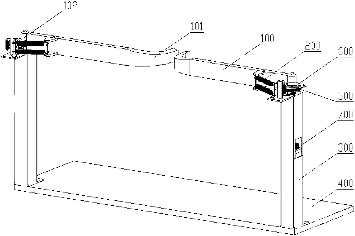
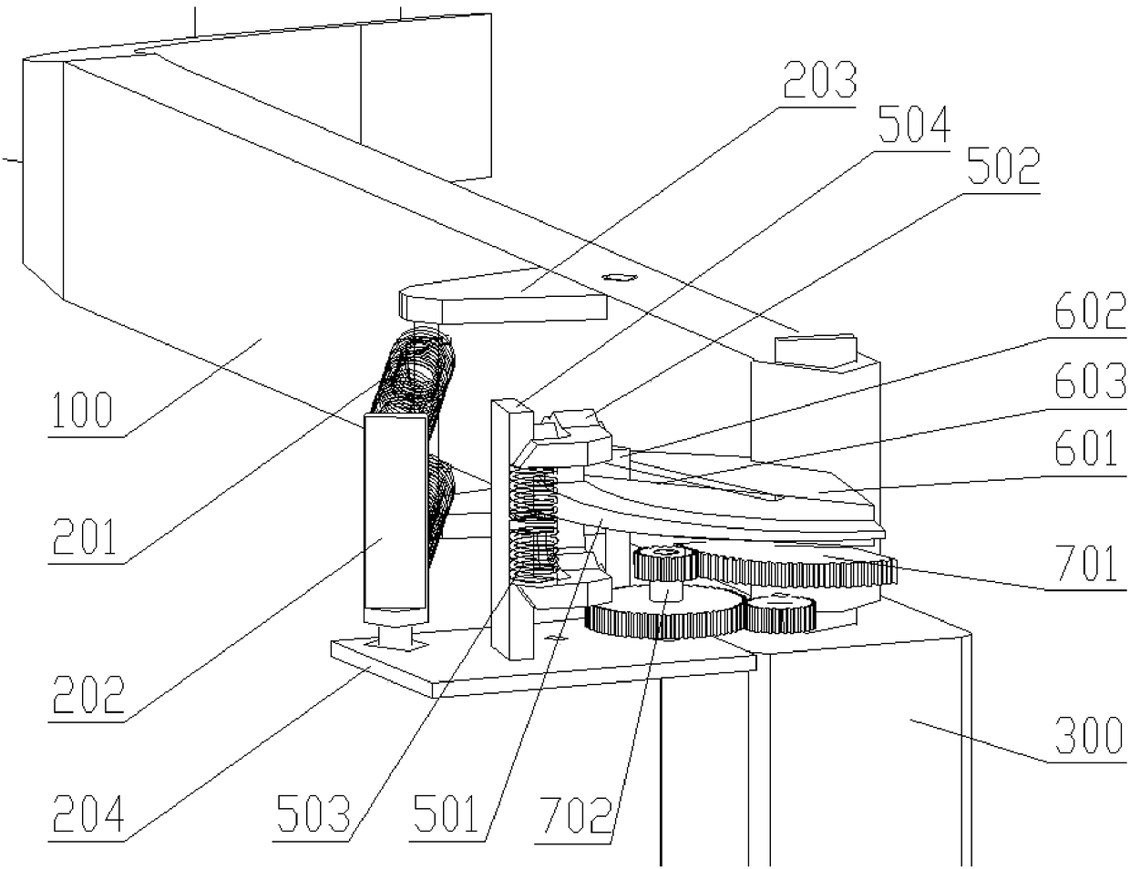
[0054] In the optional scheme of this embodiment, such as figure 1 As shown, a road warning arresting device provided in this embodiment includes an arresting rod 100, a buffer mechanism 200 and a mounting bracket 300; Rotation; one end of the buffer mechanism 200 is set on the arresting rod 100 , and is far away from the end of the arresting rod 100 which is arranged on the installation bracket 300 ; the other end of the buffer mechanism 200 is arranged on the installation bracket 300 .

[0055]In this embodiment, the length direction of the arresting rod 100 is set perpendicular to the direction of road traffic. At this time, the device is in the blocking state; The resistance produced by the blocking rod 100 will stop the violating vehicle. If the kinetic energy of the violating vehicle is greater than the resistance produced by the buffer mechanism 200 acting on the blocking rod 100, the violating vehicle will force the blocking rod 100 to deflect...

Example Embodiment

[0096] Embodiment two:

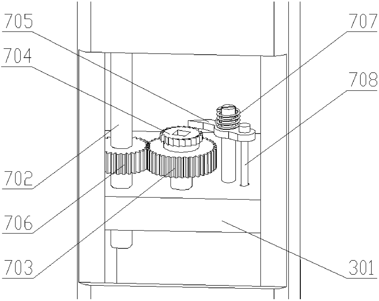
[0097] In the optional solution of this embodiment, different from the first embodiment, the state transition mechanism 700 includes a blocking state limiting hole and a passing state limiting hole; both the blocking state limiting hole and the passing state limiting hole are set on the receiving substrate 204 on.

[0098] In this embodiment, the mounting base plate 204 is rotatably arranged on the top of the mounting bracket 300, and the arresting rod rotating shaft sleeve 102 is movably connected to the mounting base plate 204 through the arresting rod rotating shaft; and the limit hole corresponding to the limit hole in the passing state; the limit hole can only be provided with one, and is combined with the blocking and passing state limit hole respectively.

[0099] When adjusted to the blocking state, the blocking state limit hole is connected with the limit hole on the top of the corresponding mounting bracket 300 through the blocking state lim...

Example Embodiment

[0100] Embodiment three:

[0101] In the optional solution of this embodiment, different from Embodiment 1 or Embodiment 2, the installation bracket 300 is only set on one side of the road, and the length of the blocking rod 100 is equal to or slightly smaller than the width of the road, so as to achieve blocking coverage for the specified height above the road. .


PUM


Abstract

The invention discloses a road alarm blocking device. The road alarm blocking device comprises a blocking rod, buffering mechanisms and a mounting support. One end of the blocking rod is rotatably arranged at the top of the mounting support and can rotate relative to the mounting support; one ends of the buffering mechanisms are arranged on the blocking rod, is away from the blocking rod and is arranged at one end of the mounting support; the other end of the buffering mechanism is arranged on the mounting support. By means of the road alarm blocking device, the length direction of the blocking rod is perpendicular to the road passing direction, and when the blocking rod is impacted by a vehicle breaking regulations, the vehicle breaking the regulations will be blocked to be stopped or pass forcedly. Explicit alarm information is given to a driver breaking traffic regulations, so that the driver actively takes measures, the occurrence probability of accidents is lowered, the accident damage degree is lowered, the purposes of blocking and the relative balance of the blocking cost are achieved, and the technical problem that by means of an existing blocking facility, accident damageis severe once an accident occurs is solved.

Description

technical field [0001] The invention relates to the technical field of road traffic safety facilities, in particular to a road warning and blocking device. Background technique [0002] At present, in the current road traffic management facilities at home and abroad, the restrictions on the passing height are mainly height-limiting poles. [0003] The use of height-limiting poles, which is an arresting method in the form of rigid impact, will result in serious damage to drivers and passengers, vehicles, and road facilities. [0004] Considering the consequences of the accident, two sets of arresting devices will also be installed in front of some key bridges and culverts. The first set of arresting devices is far away from the protection target, and its structural strength is low, while the other set of arresting devices is closer to the protection target, and its structural strength is higher. When arresting overloaded and overspeeding vehicles, when the first set of arre...

Claims


Application Information

Patent Timeline
IPC IPC(8): E01F13/04
CPCE01F13/06
Inventor 丁超师志扬
Owner 新乡市恒德机电有限公司
Why Eureka
Try Eureka