Aviation engine thrust detecting device

A technology of aero-engine and testing equipment, which is applied in the direction of engine testing, machine/structural component testing, measuring devices, etc. It can solve problems affecting the objectivity of testing, large friction, etc., and achieve the effect of stable force

Active Publication Date: 2018-08-03
绍兴市秀臻新能源科技有限公司
View PDF7 Cites 0 Cited by
  • Summary
  • Abstract
  • Description
  • Claims
  • Application Information

AI Technical Summary

Problems solved by technology

[0002] When an aero-engine leaves the factory or repairs a fault, it is necessary to perform thrust detection and related experiments to generate dynamic changes in thrust under different air pressure conditions, and determine the good condit...

Method used


Image

  • Aviation engine thrust detecting device
  • Aviation engine thrust detecting device
  • Aviation engine thrust detecting device

Examples


Embodiment Construction

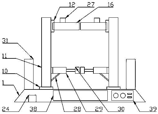
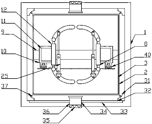
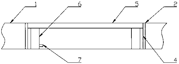
[0021] The present invention is specifically described below in conjunction with accompanying drawing, as Figure 1-5 As shown, an aero-engine thrust detection device includes a base 1, the base 1 is fixedly installed on the ground, a test hole 2 is opened in the middle of the upper surface of the base 1, and a pressure device 3 is provided in the base 1. The pressure device 3 is composed of a sliding piece 4 fitted in the test hole 2, a pressure plate 5 located in the sliding piece 4 and slidingly connected to the inner surface of the sliding piece 4, fixedly connected to the lower surface of the pressure plate 5 below the pressure plate 5, and The evenly distributed pressure sensors 6 and the signal connector 7 located on the right side of the pressure sensor 6 and fixedly connected to the middle position below the surface of the pressure sensor 6 on the right side are jointly formed. A fixing device 8 is arranged above the pressure plate 5, and the fixing device 8 The slidi...


PUM


Abstract

The invention discloses an aviation engine thrust detecting device which comprises a base. The base is fixedly arranged on the ground. A test hole is arranged in the middle of the upper surface of thebase. A pressure device is arranged in the base. The pressure device is composed of a sliding member sleeved in the test hole, a pressure plate which is located in the sliding member and is slidablyconnected with the inner surface of the sliding member, pressure sensors which are fixedly connected with the lower surface of the pressure plate and are uniformly distributed under the pressure plate, and a signal connector which is located on the right side of a pressure sensor and is fixedly connected with the lower middle of the right surface of the pressure sensor. A fixation device is arranged above the pressure plate. A fastening device is arranged above the fixation device. The aviation engine thrust detecting device provided by the invention has the advantages of simple structure andhigh practicability.

Description

technical field [0001] The invention relates to the technical field of aero-engine performance testing, in particular to an aero-engine thrust detection device. Background technique [0002] When an aero-engine leaves the factory or repairs a fault, it is necessary to perform thrust detection and related experiments to generate dynamic changes in thrust under different air pressure conditions, and determine the good condition according to the effect of thrust changes. In the test on the guide rail, because the gravity of the aero-engine is too large, even if the friction factor is small, it may bring a lot of friction, which will affect the objectivity of the test. Contents of the invention [0003] The purpose of the present invention is in order to solve above-mentioned problem, has designed a kind of aeroengine thrust detection equipment. [0004] To achieve the above object, the technical solution of the present invention is an aero-engine thrust detection device, inc...

Claims


Application Information

Patent Timeline
IPC IPC(8): G01L5/13G01M15/00
CPCG01L5/13G01M15/00
Inventor 赵国庆
Owner 绍兴市秀臻新能源科技有限公司
Why Eureka
Try Eureka