Weak current cable connection control system

A technology for connecting control and electric cables, applied in the field of weak current cable connection control system, can solve the problems of inapplicable weak current box, inconvenient travel, small entry space, etc., to avoid heat accumulation, easy installation, and easy heat dissipation.

Pending Publication Date: 2018-08-03
贵州中安智慧科技有限公司
View PDF0 Cites 4 Cited by
  • Summary
  • Abstract
  • Description
  • Claims
  • Application Information

AI Technical Summary

Problems solved by technology

[0002] Under normal circumstances, the weak current installation and construction are installed through a vertical weak current box, usually installed on a terminal board; specifically, it is connected and installed through terminal blocks, wiring frames and insulators; but for some weak current wells or tunnel openings The installation of equipment may not be suitable for the installation of weak current boxes; because the entrance space of tunnel openings or weak current wells is generally small; installing through weak current boxes or installing the overall weak current equipment, cables or terminals on a terminal board will take up more In addition, the installation of ordinary weak current boxes is messy due to too many connecting cables, and the tension between the cables cannot be adjusted. The overlapping of the lines is easy to overheat and burn the insulation and cause a short circuit; It is also very troublesome when putting the line

Method used


Image

  • Weak current cable connection control system
  • Weak current cable connection control system
  • Weak current cable connection control system

Examples


Embodiment Construction

[0026] Further detailed explanation through specific implementation mode below:

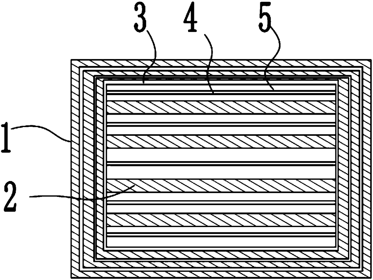
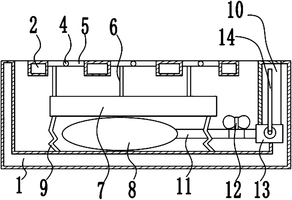
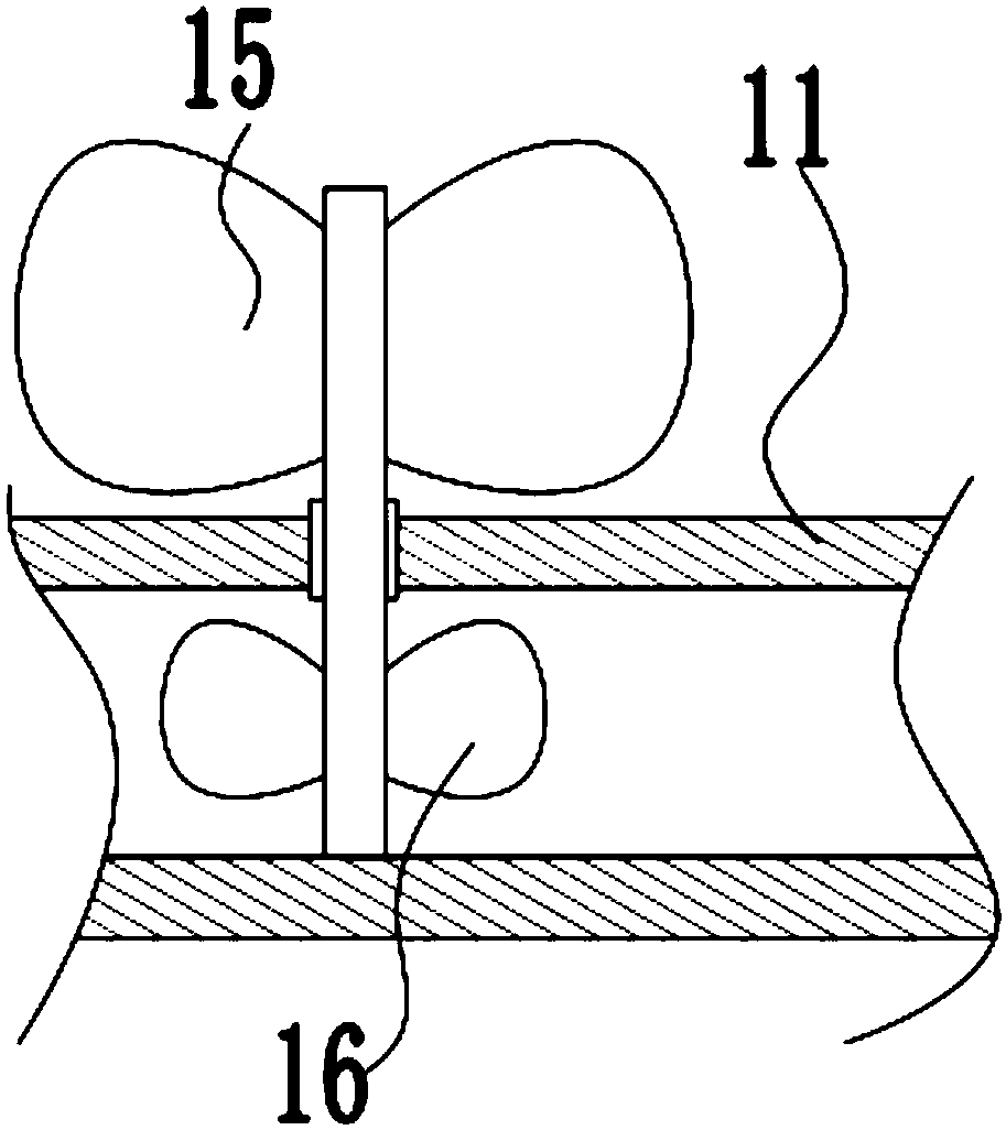
[0027] The reference signs in the drawings of the description include: installation frame 1, horizontal bar 2, deformation frame 3, strut 4, winding plate 5, connection belt 6, installation box 7, air bag 8, spring 9, cooling box 10, communication Pipe 11, fan 12, cylinder 13, rocking rod 14, outer fan 15, inner fan 16.

[0028] Such as figure 1 and figure 2 As shown, the weak current cable connection control system includes an installation frame 1 with a rectangular frame structure. The top frame of the installation frame 1 has a "mouth"-shaped opening, and the bottom plate, left side plate, and right side plate of the installation frame 1 are hollow. The flat plate structure also includes four horizontal bars 2 installed on the installation frame 1 at intervals, the hollows between the four horizontal bars 2 and the hollows between the four horizontal bars 2 and the installation frame 1, whi...


PUM


Abstract

The invention discloses a weak current cable connection control system and relates to the technical field of weak current cable installation. The weak current cable connection control system comprisesa mounting frame, wherein cross bars are arranged on the top surface of the mounting frame at intervals; cavities which are communicated with one another and filled with water are formed in the mounting frame and the cross bars; a deformable deformation frame is connected onto the top surface of the mounting frame; the deformation frame comprises a plurality of supporting rods which are arrangedat intervals and parallel to the cross bars; adjacent supporting rods are respectively positioned on two sides of the cross bars; winding plates capable of rotating around the supporting rods are connected onto the supporting rods, and the supporting rods are positioned on centerline positions of the winding plates; mounting boxes used for mounting circuit boards are arranged below all the windingplates; springs used for supporting the mounting boxes are arranged on the bottom surfaces of the mounting boxes. According to the control system disclosed by the invention, rapid installation can beperformed.

Description

technical field [0001] The invention relates to the technical field of weak current installation and connection, in particular to a weak current cable connection control system. Background technique [0002] Under normal circumstances, the weak current installation and construction are installed through a vertical weak current box, usually installed on a terminal board; specifically, it is connected and installed through terminal blocks, wiring frames and insulators; but for some weak current wells or tunnel openings The installation of equipment may not be suitable for the installation of weak current boxes; because the entrance space of tunnel openings or weak current wells is generally small; installing through weak current boxes or installing the overall weak current equipment, cables or terminals on a terminal board will take up more In addition, the installation of ordinary weak current boxes is messy due to too many connecting cables, and the tension between the cable...

Claims


Application Information

Patent Timeline
Patent Type & Authority Applications(China)
IPC IPC(8): H02G3/08H02G3/03
CPCH02G3/08H02G3/03
Inventor 李虎李松波
Owner 贵州中安智慧科技有限公司
Why Eureka
Try Eureka