Method for detecting defect coordinates on color filter

A color filter, defect coordinate technology, applied in the direction of optical testing defects/defects, etc., can solve the problems of inability to handle defects, many inspection steps, large defect coordinate errors, etc., to reduce the work cycle, accurate defect coordinates, and improve detection. The effect of efficiency

Inactive Publication Date: 2014-08-20
BOE TECH GRP CO LTD +1
View PDF8 Cites 0 Cited by
  • Summary
  • Abstract
  • Description
  • Claims
  • Application Information

AI Technical Summary

Problems solved by technology

[0003] The existing detection method has the following defects: after the color filter enters the AOI equipment, the microscope moves to read the AOI Mark, and then the TDI CCD scans the image. The reading of the AOI Mark and the TDI CCD scanning are divided into two steps. This results in many detection steps, a relatively long detection cycle, and an increase in the frequency of equipment failures, which affects the stability of the equipment; the microscope gantry and the TDI CCD gantry belong to two different gantry frames, and there are coordinate errors between them , and the defect coordinates output by the TDI CCD are based on the data calculated by the microscope, so the error of the defect coordinates will be very large, and the defects cannot be processed accurately, which will affect the quality of the product

Method used


Image

  • Method for detecting defect coordinates on color filter
  • Method for detecting defect coordinates on color filter
  • Method for detecting defect coordinates on color filter

Examples


Embodiment Construction

[0028] The specific implementation manners of the present invention will be further described in detail below in conjunction with the accompanying drawings and embodiments. The following examples are used to illustrate the present invention, but are not intended to limit the scope of the present invention.

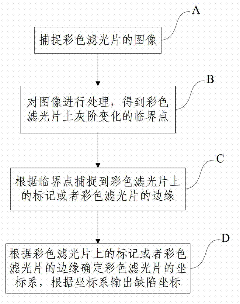
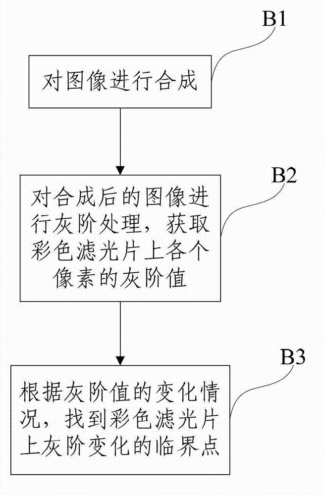
[0029] figure 2 It is a flow chart of the detection method of the defect coordinates on the color filter described in the embodiment of the present invention, as figure 2 As shown, the method comprises the steps of:

[0030] A: Capture the image of the color filter.

[0031] In this step, the image of the color filter is captured by a time-delay-integrated charge-coupled device (ie, TDI CCD), and the image has relatively high resolution. TDI CCD is suitable for imaging some high-speed moving objects. Its advantage is that the signal of multiple rows of linear array pixels is added and imaged for the same scene. Compared with ordinary linear array CCDs (especially area...


PUM


Abstract

The invention discloses a method for detecting defect coordinates on a color filter and relates to the field of industry detection. The method comprises steps of capturing an image of the color filter; processing the image and obtaining a grey scale change critical point on the color filter; capturing a mark of the color filter or an edge of the color filter in accordance with the critical point; and determining a coordinate system of the color filter in accordance with the mark of the color filter or the edge of the color filter and outputting defect coordinates in accordance with the coordinate system. The method has the advantages that a process that a microscope is used for reading a mark is omitted, the coordinate system is established and defect coordinate data are output through image processing, the working period of devices is reduced, the detection efficiency is improved and the detection accuracy of defect coordinates is improved.

Description

technical field [0001] The invention relates to the technical field of industrial detection, in particular to a method for detecting defect coordinates on a color filter. Background technique [0002] In the prior art, the detection steps for the defect coordinates on the color filter are roughly as follows: When the color filter enters the AOI (Automatic Optic Inspection, automatic optical inspection) equipment, a microscope moves to read the Mark (mark), Identify the Mark and establish the coordinate system; TDI CCD (Time Delay Integral Charge Coupled Device) scans the color filter, matches the coordinate system established by reading the Mark through the microscope through image processing, and outputs the defect coordinates. figure 1 is the schematic diagram of AOI equipment, such as figure 1 As shown, the AOI equipment 1 includes: a microscope and a TDI CCD, and the microscope is set on the microscope gantry 11 , and the TDI CCD is set on the TDI CCD gantry 12 . [00...

Claims


Application Information

Patent Timeline
Patent Type & Authority Patents(China)
IPC IPC(8): G01N21/88
Inventor 张铁轶余道平刘超强张祥
Owner BOE TECH GRP CO LTD
Why Eureka
Try Eureka